


Inclination sensor JN
26
13.4 Fault message on analogue outputs
In the event of a sensor fault (MEMS cell defective) a constant voltage of 1.0 V or
a constant current of 2 mA is provided according to the set output function (ISDU
index 660).
These values can be distinguished from the state "wire break" (0 V or 0 mA) by the
common inputs of a plant controller (PLC) and they are also considerably outside
the common value range of 2...10 V or 4...20 mA.
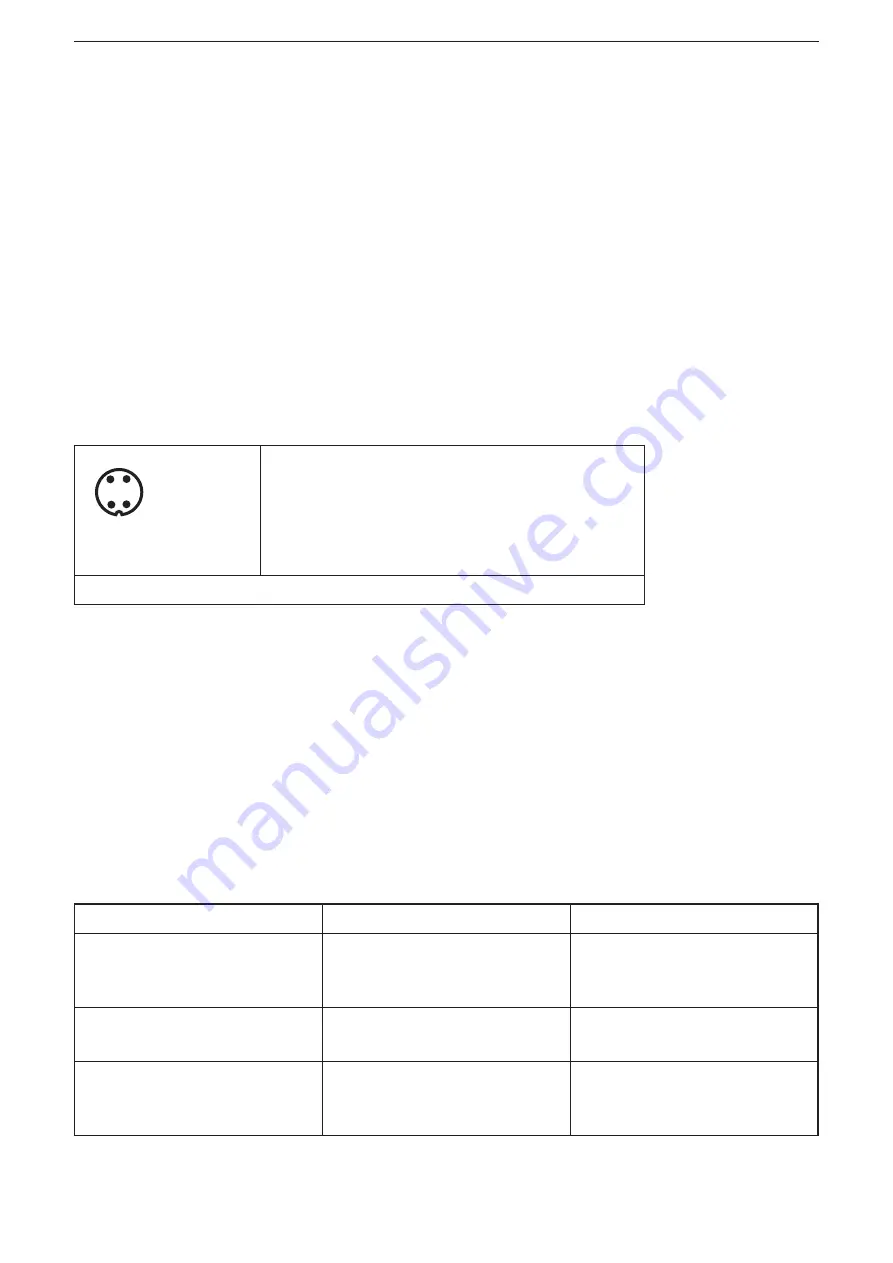
14 Parameter setting of the digital switching outputs
The sensor has two digital switching outputs (left M12 connector) which can
provide switching thresholds set by the user for the measured process values
(inclination or vibration measurement) to a machine controller (PLC), for example.
1: L+
24 V DC (+Ub-D)
2: OUT2
switching output 2
3: L-
ground (GND)
4: OUT1
switching output 1 or IO-Link
M12 connector (left)
Switching output 1 is also the communication cable for IO-Link and is referred to
as "C/Q" (Port Class A) in the IO-Link specification. Switching output 2 uses the
pin called "DI/DQ" in the IO-Link specification.
The use as switching output is only possible, if no IO-Link master tries to
communicate with the sensor and the sensor is in the SIO mode.
The assignment of the switching outputs in dependence on the selected
measuring method (ISDU index 4106) and angle calculation method (ISU index
4100) can be seen in the table below.
Measuring method
Output 1
Output 2
Inclination measurement
perpendicular
Index 4106: 0 Index 4100: 0
Perpendicular angle longitudinal
Perpendicular angle lateral
Inclination measurement Euler
Index 4106: 0
Index 4100: 1
Euler angle longitudinal
Euler angle lateral
Inclination measurement gimbal
1X
Index 4106: 0
Index 4100: 2
Gimbal angle X longitudinal
Gimbal angle X lateral


