ifm
Basic Device Manual AS-i ControllerE M4 Target V15
2015-10-30
Operating and display elements
Diagnostic LEDs
92
8
Operating and display elements
In this chapter you will become familiar with the elements on the controllere used:
to operate the device
to obtain information about the device and its configuration
to set parameters for the device and the AS-i slaves.
8.1
Diagnostic LEDs
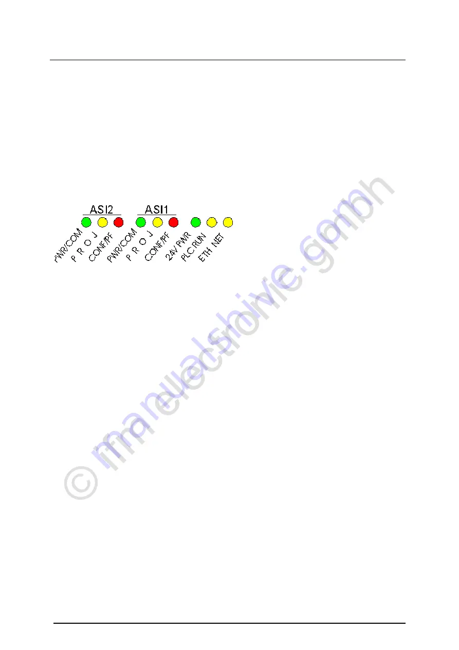
The three diagnostic LEDs on the controllere inform about the status of the AS-i masters and the
connected systems:
Figure: Diagnostic LEDs
About the figure "diagnostic LEDs":
The LEDs [ASI2] including their labelling are an option for the second AS-i master
The LED [ETH NET] including its labelling is an option for the Ethernet programming interface
Two designations for one LED, separated by a slash "/", signify:
The first designation describes the status in case of a permanently lit LED (mostly normal
operation) and
the second designation describes the status in case of a flashing LED
(mostly in case of a fault).


