background image

14

10 Operation

After power on, the unit is in the Run mode (= normal operating mode) It carries 

out its measurement and evaluation functions and provides output signals accord-

ing to the set parameters

Operating indications → Chapter 7 Operating and display elements.

10.1 Reading of the set parameters

Press [Mode/Enter] until the requested parameter is displayed


Press [Set] briefly


The unit displays the corresponding parameter value for about 15 s After 


>

another 15 s the unit returns to the Run mode

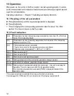
10.2 Fault indication

[OL]

Temperature too high (measuring range exceeded by more than 3% of the final 

value of the measuring range)

[UL]

Temperature too low (measuring range below the final value of the measuring 

range by more than 10%)

[Err]

No temperature sensor connected

• 

Fault or short circuit in the temperature sensor, wire break

• 

Detection zone is exceeded (T < -60°C or T > +160°C)

• 

[SC1]

Short circuit in OUT1*

[SC2]

Short circuit in OUT2*

[SC]

Short circuit in both switching outputs*

[Loc]

Setting pushbuttons of the unit locked, parameter change rejected

[SLoc] Unit locked via software, parameter change rejected
[PARA]

Setting value of a parameter outside the valid range → the unit is not ready for 

operation The error may occur with IO-Link parameter setting

If an invalidly set parameter is activated, [PARA] is displayed instead of the 

parameter value

*The output concerned is switched off as long as the short circuit exists

The messages Err, PARA and SC1 are shown even if the display is switched off

Содержание TR7432

Страница 1: ...Operating instructions Control monitor for temperature sensors TR7432 704469 00 10 2008 UK...

Страница 2: ...the display optional 12 9 3 Setting of the output signals 12 9 3 1 Setting of the output function 12 9 3 2 Setting of the switching limits 12 9 4 User settings optional 12 9 4 1 Setting the measuremen...

Страница 3: ...r application without any restrictions Improper or non intended use may lead to malfunctions of the unit or to un wanted effects in your application That is why installation electrical connec tion set...

Страница 4: ...ng signal for system temperature limit value OUT2 Switching signal for system temperature limit value It moreover provides the process data via IO Link The unit is laid out for fully bidirectional com...

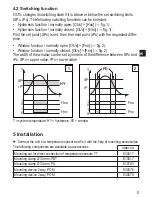
Страница 5: ...x Fno fig 2 Window function normally closed OUx Fnc fig 2 The width of the window can be set by means of the difference between SPx and rPx SPx upper value rPx lower value 1 2 T system temperature HY...

Страница 6: ...dhered to Voltage supply to EN 50178 SELV PELV Disconnect power Connect the unit as follows 1 two wire sensor 2 three wire sensor 3 four wire sensor connection for voltage supply and output signals Pi...

Страница 7: ...Mmod 4w Core colours of ifm sockets 1 BN brown 2 WH white 3 BU blue 4 BK black 7 Operating and display elements 1 to 8 Indicator LEDs LED 1 Current temperature in C LED 2 Current temperature in F LED...

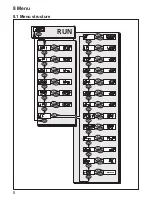
Страница 8: ...8 8 Menu 8 1 Menu structure...

Страница 9: ...unction H or window function F either normally open no or normally closed nc Mmod Measurement method 2 wire 3 wire or 4 wire temperature sensors EF Extended functions opening of menu level 2 HI Maximu...

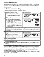
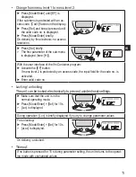
Страница 10: ...t the dis play move to the maximum setting value Then the cycle starts again at the minimum setting value 3 Acknowledgement of the parameter value Press Mode Enter briefly The parameter is displayed a...

Страница 11: ...program Activate the EF button If menu level 2 is protected by an access code the input field for the code no is activated Enter valid code no Locking unlocking The unit can be locked electronically t...

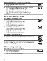
Страница 12: ...n normally open Hnc Hysteresis function normally closed Fno Window function normally open Fnc Window function normally closed Select OU2 and set the function Hno Hysteresis function normally open Hnc...

Страница 13: ...set the value On Output 1 2 switches ON in case of a fault OFF Output 1 2 switches OFF in case of a fault 9 4 5 Setting of the switching logic for OUT1 Select P n and set PnP or nPn 9 5 Service funct...

Страница 14: ...e too low measuring range below the final value of the measuring range by more than 10 Err No temperature sensor connected Fault or short circuit in the temperature sensor wire break Detection zone is...

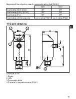
Страница 15: ...Invalid setting OU1 OU2 OFF OFF Invalid setting FOU1 FOU2 OFF OFF Invalid setting P n OFF OFF Invalid setting of other parameters acc to setting FOU1 acc to setting FOU2 11 Scale drawing Dimensions in...

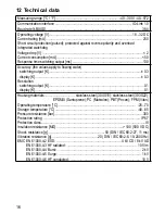
Страница 16: ...tput K 0 3 display K 0 3 Resolution switching output K 0 1 display K 0 1 Housing materials stainless steel 304S15 stainless steel 303S22 EPDM X Santoprene PC Makrolon PBT Pocan FPM Viton Operating tem...

Страница 17: ...F 39 6 572 0 40 0 571 6 0 1 T step increment 13 Factory setting Factory setting User setting SP1 60 0 rP1 50 0 OU1 Hno OU2 Hno SP2 120 0 rP2 100 0 Mmod 4w COF 0 0 dS1 0 0 dr1 0 0 dS2 0 0 dr2 0 0 FOU1...

Отзывы: