background image


E2D400 Series Panel PC 

Page 113 


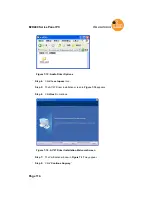
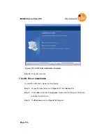
Figure 7-14: VGA Driver Installation Finish Screen 

7.5 Audio Driver Installation 

To install the audio driver, please do the following. 

Step 1: 

Access the driver list shown in 

Figure 7-1

. (See 

Section 7.2

Step 2: 

Click “

Audio

” 

Step 3: 

The screen in 

Figure 7-15

 appears. Double click the “WDM_A404” folder. 

Содержание E2D400 Series

Страница 1: ...E2D400 Series Panel PC Page I MODEL User Manual Touch Panel PC E2D400 E2D400 00 01 2013...

Страница 2: ...arising out of the use or inability to use the product or documentation even if advised of the possibility of such damages This document contains proprietary information protected by copyright All ri...

Страница 3: ...FOR E2D400 Translation This a Class B product based on the standard of the VCCI Council If this is used near a radio or television receiver in a domestic environment it may cause radio interference I...

Страница 4: ...ot occur in a particular installation If this equipment does cause harmful interference to radio or television reception which can be determined by turning the equipment off and on the user is encoura...

Страница 5: ...endor you purchased the E2D400 series from or contact an ifm electronic GmbH sales representative directly The items listed below should all be included in the E2D400 series package 1 x ifm electronic...

Страница 6: ...iew 6 1 4 System Specifications 7 2 Detailed Specifications 9 2 1 Dimensions 10 2 2 Intel Atom Processor 11 2 3 Motherboard Components 11 2 3 1 Memory Support 11 2 3 2 Storage Capacity 12 2 4 External...

Страница 7: ...4 5 Removing the Back Cover 27 4 6 CF Card Installation 28 4 7 HDD Installation 29 4 8 AT ATX Mode Selection 30 4 8 1 AT Power Mode 30 4 8 2 ATX Power Mode 31 4 9 Jumper Settings 31 4 9 1 Access the...

Страница 8: ...moval 54 5 5 Replacing Components 55 5 5 1 Memory Module Replacement 55 5 5 2 CF Card Replacement 56 5 6 Reinstalling the Covers 57 6 AMI BIOS Setup 58 6 1 Introduction 59 6 1 1 Starting Setup 59 6 1...

Страница 9: ...ation 94 6 7 2 SouthBridge Configuration 97 6 8 Exit 98 7 Software Drivers 101 7 1 Available Software Drivers 102 7 2 Starting the Driver Program 102 7 3 Chipset Driver Installation 103 7 4 VGA Driver...

Страница 10: ......

Страница 11: ...E2D400 Series Panel PC Page 1 1 Introduction Chapter 1...

Страница 12: ...th an Intel ICH7 M input output controller hub ensures optimal memory graphics and peripheral I O support The system comes with 1 0 GB of preinstalled DDR2 SDRAM and supports a maximum of 2 0 GB of DD...

Страница 13: ...yet sophisticated systems that are easily implemented in commercial environments industrial environments and corporate environments 1 2 External Overview 1 2 1 General Description The stylish E2D400 p...

Страница 14: ...is a flat panel TFT LCD screen with LED backlight surrounded by an ABS PC plastic frame The top of the front panel has a power LED Figure 1 2 E2D400 Front View 1 2 3 Rear Panel The rear panel provides...

Страница 15: ...e following I O interface connectors 1 x Audio connector 1 x 12 V DC In connector 1 x External SATA connector 1 x RS 232 connector 1 x RS 232 422 485 connector 2 x LAN connectors 4 x USB 2 0 connector...

Страница 16: ...eries provides access to slots that support panel mount and rack mount Figure 1 5 Figure 1 5 E2D400 Top View Figure 1 6 Side View 1 3 Internal Overview The E2D400 has the following components installe...

Страница 17: ...MHz DDR2 SDRAM SO DIMM pre installed Supports up to 2 GB 533 400 MHz DDR2 SDRAM SSD slot 4 GByte CompactFlash Type II preinstalled Watchdog Timer Software Programmable supports 1 sec 255 sec system r...

Страница 18: ...istive Type 5 wire touch controller is on board 50 W Input 90 VAC 264 VAC 50 Hz 60 Hz Power Adapter Output 12 V DC Power Consumption 32 W 1 x 12 V DC input jack 1 x Audio connector 1 x RS 232 COM port...

Страница 19: ...E2D400 Series Panel PC Page 9 2 Detailed Specifications Chapter 2...

Страница 20: ...ge 10 E2D400 Series Panel PC 2 1 Dimensions The following section provides detailed schematics and information on the dimensions of the E2D400 series Figure 2 1 E2D400 Top and Bottom Panel Dimensions...

Страница 21: ...SIMD Extensions 2 and 3 Intel SSE2 and Intel SSE3 support and Supplemental Streaming SIMD Extension 3 SSSE3 support Micro FCBGA8 packaging technologies Thermal management support via Intel Thermal Mo...

Страница 22: ...scuss the necessary system requirement 2 3 2 Storage Capacity The E2D400 series supports an easily installed CompactFlash Type II CF Type II memory disk The E2D400 also supports a SATA drive through t...

Страница 23: ...l ring RI signal or can be designated as a 5 V or 12 V power supply Enabling COM devices to be powered through the COM port eliminates unnecessary and messy cabling Figure 2 3 COM Ports 2 4 2 LAN Conn...

Страница 24: ...ansmit Receive on chip buffer support 64 pin QFN package Green package 2 4 3 External USB Connectors There are four USB 2 0 connectors on the bottom panel of the E2D400 All USB 2 0 connectors are inte...

Страница 25: ...durable 2 6 Audio 2 6 1 AC 97 Audio Codec Controller The integrated AC 97 Audio compliant audio controller on the Intel ICH7 Southbridge is integrated to a RealTek ALC655 audio codec The RealTek ALC65...

Страница 26: ...e run in the AT power mode or the ATX power mode Both these power modes are described below 2 7 1 1 ATX Power Mode Default With the ATX mode selected the E2D400 panel PC goes in a standby mode when it...

Страница 27: ...iple panel PCs from a central management center and other applications including ATM Self service kiosk Plant environment monitoring system Factory automation platform Manufacturing shop flow 2 7 2 Po...

Страница 28: ...eripheral devices through a Bluetooth network The peripheral devices may include Headsets Barcode readers PDA Printers Cell phones Keyboard and mouse The technical specifications of the Bluetooth modu...

Страница 29: ...E2D400 Series Panel PC Page 19 Figure 2 10 PIFA Antenna and Wireless Module...

Страница 30: ...Page 20 E2D400 Series Panel PC 3 Unpacking Chapter 3...

Страница 31: ...he installation process Step 1 Use box cutters a knife or a sharp pair of scissors that seals the top side of the external second box Step 2 Open the external second box Step 3 Use box cutters a knife...

Страница 32: ...l PC 3 1 1 Packing List The E2D400 flat panel PC is shipped with the following components Quantity Item Image Standard 1 E2D400 series 1 Power adapter 1 Power cord 1 SATA and power cable 1 Screw kit 1...

Страница 33: ...00 Series Panel PC Page 23 1 Touch pen Optional Panel mounting kit E2D402 Wall mounting kit E2D401 If any of these items are missing or damaged contact the distributor or sales representative immediat...

Страница 34: ...Page 24 E2D400 Series Panel PC 4 Installation Chapter 4...

Страница 35: ...revent ESD from damaging the board Self grounding Before handling the board touch any grounded conducting material During the time the board is handled frequently touch any conducting materials that a...

Страница 36: ...oard TFT LCD screen 1 0 GB DDR2 memory module Resistive type touch screen Wireless LAN module Bluetooth module AT ATX power switch 4 GByte CompactFlash Type II Component installation is described in t...

Страница 37: ...k cover must be removed To remove the back cover please follow the steps below Step 5 Remove the retention screws Figure 4 1 and lift the cover off the flat panel PC Figure 4 1 Back Cover Retention Sc...

Страница 38: ...inside the rear panel To install the CF card follow the instructions below Step 1 Locate the CF slot Insert a CF card into the slot Figure 4 3 Figure 4 3 CF Card Location Step 2 Replace the plastic ba...

Страница 39: ...he four retention screw holes in the both sides of the HDD bracket with the retention screw holes on the sides of the HDD Insert four retention screws into the HDD bracket Figure 4 5 Figure 4 5 HDD Re...

Страница 40: ...t AT mode or ATX mode follow the steps below Step 1 Remove the plastic back cover See Section 4 5 above Step 2 Locate the AT ATX switch on the aluminum chassis Figure 4 6 Figure 4 6 AT ATX Switch Loca...

Страница 41: ...applications since the broadcasting time for each panel PC can be set individually and controlled remotely Other possible application includes Security surveillance Point of Sale POS Advertising term...

Страница 42: ...M3 Pin 9 setting JP10 6 pin header COM3 RX RS 232 422 485 select JP9 8 pin header COM3 TX RS 422 485 select JP11 6 pin header COM3 RS 232 422 485 select JP6 12 pin header Table 4 1 Jumpers 4 9 1 Acces...

Страница 43: ...lear CMOS jumper clears the CMOS data and resets the system BIOS information To do this use the jumper cap to close the pins for a few seconds then remove the jumper clip If the CMOS Settings Wrong me...

Страница 44: ...tings See Table 4 4 Jumper Location See Figure 4 8 Two jumpers JP8 and JP10 configure pin 9 on COM1 and COM3 DB 9 connectors Pin 9 on the COM1 and the COM3 DB 9 connectors can be set as the ring RI si...

Страница 45: ...3 Pin 9 Setting Jumper Settings The COM1 and COM3 Pin 9 Setting jumper locations are shown in Figure 4 8 below Figure 4 8 COM1 and COM3 Pin 9 Setting Jumper Locations 4 9 4 1 COM3 RS 422 and RS 485 Pi...

Страница 46: ...tion See Figure 4 9 The COM3 RX Function Select jumper sets the communication protocol used by the RX serial communications port COM3 as RS 232 RS 422 or RS 485 The COM3 RX Function Select jumper sett...

Страница 47: ...COM3 TX Function Select jumper configures the TX pin on COM3 serial port connector as RS 422 as an RS 485 The COM3 TX Function Select jumper selection options are shown in Table 4 9 COM3 TX Function...

Страница 48: ...0 Jumper Location See Figure 4 11 The COM3 RS 232 422 485 Serial Port Select jumper sets the communication protocol used by the second serial communications port COM3 as RS 232 RS 422 or RS 485 The CO...

Страница 49: ...ure 4 11 Figure 4 11 COM3 RS 232 422 485 Serial Port Select Jumper Location 4 10 Mounting the System WARNING When mounting the flat panel PC onto an arm onto the wall or onto a panel it is better to h...

Страница 50: ...he location on the wall for the wall mounting bracket Step 2 Carefully mark the locations of the four screw holes in the bracket on the wall Step 3 Drill four pilot holes at the marked locations on th...

Страница 51: ...the M4 screws provided in the wall mount kit for the rear panel If the screw is missing the thread depth of the replacement screw should be not more than 4 mm Step 7 Align the mounting screws on the...

Страница 52: ...Page 42 E2D400 Series Panel PC NOTE In the diagram below the bracket is already installed on the wall Figure 4 13 Chassis Support Screws Step 0...

Страница 53: ...aller than the overall size of the frame that surrounds the flat panel PC but just large enough for the rear panel of the flat panel PC to fit through see Fehler Verweisquelle konnte nicht gefunden we...

Страница 54: ...ries on an arm please follow the steps below Step 1 The arm is a separately purchased item Please correctly mount the arm onto the surface it uses as a base To do this refer to the installation docume...

Страница 55: ...ion screw holes are shown in Figure 4 16 Figure 4 16 E2D400 Arm Mounting Retention Screw Holes Step 4 Secure the flat panel PC to the interface pad by inserting four retention screws through the botto...

Страница 56: ...e rack cabinet bracket until the aluminum frame is flush against the front of the bracket Figure 4 17 Figure 4 17 The Rack Cabinet Bracket Step 2 Insert the rack mounting clamps into the pre formed ho...

Страница 57: ...ies Panel PC Page 47 Figure 4 18 Secure the Rack Cabinet Bracket Step 4 Slide the flat panel PC with the attached rack cabinet bracket into a rack or cabinet Figure 4 19 Figure 4 19 Install into a Rac...

Страница 58: ...rs 4 11 1 LAN Connection There are two external RJ 45 LAN connectors The RJ 45 connector enables connection to an external network To connect a LAN cable with an RJ 45 connector please follow the inst...

Страница 59: ...low the steps below to connect a serial device to the E2D400 Series panel PC Step 1 Locate the DB 9 connector The location of the DB 9 connector is shown in Chapter 2 Step 2 Insert the serial connecto...

Страница 60: ...elow Step 1 Located the USB connectors The locations of the USB connectors are shown in Chapter 2 Step 2 Align the connectors Align the USB device connector with one of the connectors on the bottom pa...

Страница 61: ...E2D400 Series Panel PC Page 51 5 System Maintenance Chapter 5...

Страница 62: ...ctrostatic discharge ESD can cause serious damage to electronic components including the E2D400 Dry climates are especially susceptible to ESD It is therefore critical that whenever the E2D400 is acce...

Страница 63: ...e sure the system is turned off 5 4 Opening the System 5 4 1 Removing the Back Cover WARNING Over tightening back cover screws will crack the plastic frame Maximum torque for cover screws is 5 kg cm 0...

Страница 64: ...ng the retention screws Figure 4 2 More strength is required to separate the cover from the chassis Step 0 Figure 5 2 E2D400 Plastic Back Cover Removal 5 4 2 E2D400 Series Internal Aluminum Cover Remo...

Страница 65: ...5 1 Memory Module Replacement The flat panel PC is preinstalled with a 1 GB DDR2 memory module If the memory module fails follow the instructions below to replace the memory module Step 1 Remove the b...

Страница 66: ...socket at an angle Figure 5 5 Step 7 Gently pull the spring retainer clips of the SO DIMM socket out and push the rear of the DDR memory module down Figure 5 5 Step 8 Release the spring retainer clip...

Страница 67: ...ed in Section 4 6 to replace the CF card Step 0 5 6 Reinstalling the Covers WARNING Failing to reinstall the covers may result in permanent damage to the system Please make sure all coverings are prop...

Страница 68: ...Page 58 E2D400 Series Panel PC 6 AMI BIOS Setup Chapter 6...

Страница 69: ...ss the DELETE key when the Press Del to enter SETUP message appears on the screen 0 If the message disappears before the DELETE key is pressed restart the computer and try again 6 1 2 Using Setup Use...

Страница 70: ...ow press ESC or the F1 key again 6 1 4 Unable to Reboot After Configuration Changes If the computer cannot boot after changes to the system configuration is made CMOS defaults Use the jumper described...

Страница 71: ...he System Overview lists a brief summary of different system components The fields in System Overview cannot be changed The items shown in the system overview include AMI BIOS Displays auto detected B...

Страница 72: ...m date Manually enter the day month and year 6 3 Advanced Use the Advanced menu 865HBIOS Menu 2 to configure the CPU and peripheral devices through the following sub menus WARNING Setting the wrong va...

Страница 73: ...E2D400 Series Panel PC Page 63 BIOS Menu 2 Advanced 6 3 1 CPU Configuration Use the CPU Configuration menu 873HBIOS Menu 3 to view detailed CPU specifications and configure the CPU...

Страница 74: ...U manufacturer Brand String Lists the brand name of the CPU being used Frequency Lists the CPU processing speed FSB Speed Lists the FSB speed Cache L1 Lists the CPU L1 cache size Cache L2 Lists the CP...

Страница 75: ...ler Compatible DEFAULT Configures the on board ATA IDE controller to be in compatible mode In this mode a SATA channel will replace one of the IDE channels This mode supports up to 4 storage devices E...

Страница 76: ...the auto detected IDE devices The following IDE devices are detected and are shown in the IDE Configuration menu Primary IDE Master Primary IDE Slave Secondary IDE Master Secondary IDE Slave The IDE C...

Страница 77: ...ted as follows Device Lists the device type e g hard disk CD ROM etc Type Indicates the type of devices a user can manually select Vendor Lists the device manufacturer Size List the storage capacity o...

Страница 78: ...pe BIOS option select the type of device the AMIBIOS attempts to boot from after the Power On Self Test POST is complete Not Installed BIOS is prevented from searching for an IDE disk drive on the spe...

Страница 79: ...led BIOS is prevented from using Multi Sector Transfer on the specified channel The data to and from the device occurs one sector at a time Auto DEFAULT BIOS auto detects Multi Sector Transfer support...

Страница 80: ...value if the IDE disk drive support cannot be determined SWDMA0 Single Word DMA mode 0 selected with a maximum data transfer rate of 2 1MBps SWDMA1 Single Word DMA mode 1 selected with a maximum data...

Страница 81: ...an 80 conductor ATA cable is used S M A R T Auto Use the S M A R T option to auto detect disable or enable Self Monitoring Analysis and Reporting Technology SMART on the drive on the specified channe...

Страница 82: ...Configuration Serial Port1 Address 3F8 IRQ4 Use the Serial Port1 Address option to select the Serial Port 1 base address Disabled No base address is assigned to Serial Port 1 3F8 IRQ4 DEFAULT Serial P...

Страница 83: ...Serial Port3 Address option to select the Serial Port 3 base address Disabled No base address is assigned to Serial Port 3 3E8 DEFAULT Serial Port 3 I O port address is 3E8 2E8 Serial Port 3 I O port...

Страница 84: ...to select the interrupt address for serial port 4 10 DEFAULT Serial port 4 IRQ address is 10 6 3 4 Hardware Health Configuration The Hardware Health Configuration menu 879HBIOS Menu 7 shows the operat...

Страница 85: ...e PWM Manual Mode the following parameters can be set CPU Fan PWM control CPU Temp Limit of OFF 000 WARNING Setting this value too high may cause the fan to stop when the CPU is at a high temperature...

Страница 86: ...ecified in the Fan 3 Start PWM option below To select a value select the CPU Temp Limit of Start option and enter a decimal number between 000 and 127 The temperature range is specified below Minimum...

Страница 87: ...available options is shown below 0 125 PWM 0 25 PWM 0 5 PWM 1 PWM 2 PWM 4 PWM 8 PWM 15 PWM The following system parameters and values are shown The system parameters that are monitored are System Temp...

Страница 88: ...enu 880HBIOS Menu 8 configures the Advanced Configuration and Power Interface ACPI and Power Management APM options BIOS Menu 8 Power Configuration 6 3 5 1 ACPI configuration The ACPI Configuration me...

Страница 89: ...s not being used S1 POS DEFAULT System appears off The CPU is stopped RAM is refreshed the system is running in a low power mode S3 STR System appears off The CPU has no power RAM is in slow refresh t...

Страница 90: ...the Restore on AC Power Loss BIOS option to specify what state the system returns to if there is a sudden loss of power to the system Power Off The system remains turned off Power On The system turns...

Страница 91: ...is roused when the mouse is moved or a button on the keyboard is pressed Disabled DEFAULT Wake event not generated by activity on the keyboard or mouse Resume On KeyBoard Wake event not generated by a...

Страница 92: ...on to specify the time the system should be roused from a suspended state Disabled DEFAULT The real time clock RTC cannot generate a wake event Enabled If selected the following appears with values th...

Страница 93: ...Access option to enable or disable access to the remote functionalities of the system Disabled DEFAULT Remote access is disabled Enabled Remote access configuration options shown below appear Serial...

Страница 94: ...ase Address IRQ option cannot be configured and only shows the interrupt address of the serial port listed above Serial Port Mode 115200 8 n 1 Use the Serial Port Mode option to select baud rate throu...

Страница 95: ...e OSes may not work if set to Always Terminal Type ANSI Use the Terminal Type BIOS option to specify the remote terminal type ANSI DEFAULT The target terminal type is ANSI VT100 The target terminal ty...

Страница 96: ...Support BIOS option to enable USB mouse and USB keyboard support Normally if this option is not enabled any attached USB mouse or USB keyboard does not become available until a USB compatible operatin...

Страница 97: ...DEFAULT The controller is capable of operating at high speed 480 Mb s 6 4 PCI PnP Use the PCI PnP menu 884HBIOS Menu 13 to configure advanced PCI and PnP settings WARNING Setting wrong values for the...

Страница 98: ...ified IRQ is reserved for use by Legacy ISA devices Available IRQ addresses are IRQ3 IRQ4 IRQ5 IRQ7 IRQ9 IRQ10 IRQ 11 IRQ 14 IRQ 15 DMA Channel Available Use the DMA Channel option to assign a specifi...

Страница 99: ...BIOS option to specify the amount of memory that should be reserved for legacy ISA devices Disabled DEFAULT No memory block reserved for legacy ISA devices 16K 16KB reserved for legacy ISA devices 32K...

Страница 100: ...nu 886HBIOS Menu 15 to configure advanced system boot options BIOS Menu 15 Boot Settings Configuration Quick Boot Enabled Use the Quick Boot BIOS option to make the computer speed up the boot process...

Страница 101: ...Allows the computer system to display the information during system boot Bootup Num Lock On The Bootup Num Lock BIOS option allows the Number Lock setting to be modified during boot up Off Does not en...

Страница 102: ...om LAN Support option enables the system to be booted from a remote system Enabled Can be booted from a remote system through the LAN Disabled DEFAULT Cannot be booted from a remote system through the...

Страница 103: ...or Password Change User Password Use the Change User Password to set or change a user password The default for this option is Not Installed If a user password must be installed select this field and e...

Страница 104: ...ge 94 E2D400 Series Panel PC BIOS Menu 17 Chipset 6 7 1 North Bridge Chipset Configuration Use the North Bridge Chipset Configuration menu BIOS Menu 18890H to configure the Northbridge chipset setting...

Страница 105: ...n card is used please refer to the documentation that came with the card to see if it is necessary to reserve the space Disabled DEFAULT Memory is not reserved for ISA expansion cards Enabled Memory i...

Страница 106: ...memory If more memory is needed graphics memory is dynamically allocated according to the system and graphics needs DVMT FIXED Memory Use the DVMT FIXED Memory option to specify the maximum amount of...

Страница 107: ...FAULT LFP Panel Type by H W Use the LFP Panel Type option to select the type of flat panel connected to the system Configuration options are listed below 640x480 18b 800x480 18b 800x600 18b 1024x768 1...

Страница 108: ...io Controller option enables or disables the audio controller AC 97 Audio Only The on board AC 97 audio controller is enabled All Disabled DEFAULT The on board audio controller is disabled 6 8 Exit Us...

Страница 109: ...se the Discard Changes and Exit option to exit the BIOS configuration setup program without saving the changes made to the system Discard Changes Use the Discard Changes option to discard the changes...

Страница 110: ...100 E2D400 Series Panel PC Load Failsafe Defaults Use the Load Failsafe Defaults option to load failsafe default values for each of the parameters on the Setup menus F8 key can be used for this opera...

Страница 111: ...E2D400 Series Panel PC Page 101 7 Software Drivers Chapter 7...

Страница 112: ...n the system Chipset VGA Audio LAN Touch screen Bluetooth Wireless Installation instructions are given below 7 2 Starting the Driver Program To access the driver installation programs please do the fo...

Страница 113: ...Chipset Driver Installation To install the chipset driver please do the following Step 1 Access the driver list shown in Figure 7 1 See Section 7 2 Step 2 Click Chipset and double click Setup exe Step...

Страница 114: ...Page 104 E2D400 Series Panel PC Figure 7 2 Chipset Driver Screen Step 4 When the setup files are completely extracted the Welcome Screen in Figure 7 3 appears Figure 7 3 Chipset Driver Welcome Screen...

Страница 115: ...continue Step 6 The license agreement in Figure 7 4 appears Step 7 Read the License Agreement Step 8 Click the Yes icon to continue Figure 7 4 Chipset Driver License Agreement Step 9 The Read Me file...

Страница 116: ...Page 106 E2D400 Series Panel PC Figure 7 5 Chipset Driver Read Me File Step 11 Setup Operations are performed as shown in Figure 7 6...

Страница 117: ...ipset Driver Setup Operations Step 12 Once the Setup Operations are complete click the Next icon to continue Step 13 The Finish screen appears Step 14 Select Yes I want to restart the computer now and...

Страница 118: ...7 4 VGA Driver Installation To install the VGA driver please do the following Step 1 Access the driver list shown in Figure 7 1 See Section 7 2 Step 2 Click VGA and double click the win2k_xp14324 exe...

Страница 119: ...ries Panel PC Page 109 Figure 7 8 VGA Driver Read Me File Step 5 The installation files are extracted See Figure 7 9 Figure 7 9 VGA Driver Setup Files Extracted Step 6 The Welcome Screen in Figure 7 1...

Страница 120: ...400 Series Panel PC Figure 7 10 VGA Driver Welcome Screen Step 7 Click Next to continue Step 8 The license agreement in Figure 7 11 appears Step 9 Read the License Agreement Step 10 Click the Yes icon...

Страница 121: ...ge 111 Figure 7 11 VGA Driver License Agreement Step 11 The Read Me file in Figure 7 12 appears Step 12 Click Next to continue Figure 7 12 VGA Driver Read Me File Step 13 Setup Operations are performe...

Страница 122: ...VGA Driver Setup Operations Step 14 Once the Setup Operations are complete click the Next icon to continue Step 15 The Finish screen appears Step 16 Select Yes I want to restart the computer now and c...

Страница 123: ...lation Finish Screen 7 5 Audio Driver Installation To install the audio driver please do the following Step 1 Access the driver list shown in Figure 7 1 See Section 7 2 Step 2 Click Audio Step 3 The s...

Страница 124: ...tep 4 Click the setup exe icon Step 5 The AC 97 Driver Installation screen in Figure 7 16 appears Step 6 Click Next to continue Figure 7 16 AC 97 Driver Installation Welcome Screen Step 7 The Verifica...

Страница 125: ...erification Step 9 The driver installation begins See Figure 7 18 Figure 7 18 AC 97 Driver Installation Step 10 When the driver is installed the driver installation finish screen in Figure 7 19 appear...

Страница 126: ...tep 0 7 6 LAN Driver Installation To install the LAN driver please do the following Step 1 Access the driver list shown in Figure 7 1 See Section 7 2 Step 2 Click LAN and locate the setup exe Double c...

Страница 127: ...Page 117 Figure 7 20 LAN Driver Welcome Screen Step 4 Click Next to continue Step 5 The Ready to Install screen in Figure 7 21 appears Step 6 Click Next to proceed with the installation Figure 7 21 LA...

Страница 128: ...program begins to install Step 8 The installation progress can be monitored in the progress bar shown in Figure 7 22 Figure 7 22 LAN Driver Installation Step 9 When the driver installation is complet...

Страница 129: ...elow Step 1 Access the driver list shown in Figure 7 1 See Section 7 2 Step 2 Click Touch Screen Open the x Touch PenMount Windows Universal Driver V2 0 0 107 directory and locate the icon for the Set...

Страница 130: ...Step 4 The license agreement shown in Figure 7 25 appears Agree to the license by selecting I accept the terms in the license agreement Figure 7 25 License Agreement Step 5 Click NEXT and the Install...

Страница 131: ...alling PenMount DMC9000 screen appears as the program is installed Figure 7 27 Figure 7 27 Installing PenMount DMC9000 Step 7 The user is then prompted to select to restart the computer now or later F...

Страница 132: ...the Computer 7 8 Bluetooth Driver To install the Bluetooth software driver please follow the steps below Step 1 Select Bluetooth from the list in Figure 7 1 Step 2 A new window opens Figure 7 29 Clic...

Страница 133: ...welcome screen appears Figure 7 30 To continue the installation process click NEXT Figure 7 30 Welcome Screen Step 4 The license agreement shown in Figure 7 31 appears Agree to the license by selectin...

Страница 134: ...appears next Figure 7 32 Bluetooth Driver Setup Options Step 6 Select the required installation configuration in Figure 7 32 and click NEXT to continue Step 7 The Destination Folder screen in Figure 7...

Страница 135: ...stination Folder Step 8 Click NEXT and the Installshield Wizard is ready to install the program Figure 7 34 Figure 7 34 Ready to Install the Program Step 9 Click INSTALL to continue The Installing Blu...

Страница 136: ...igure 7 36 Figure 7 36 Bluetooth Driver Complete Installation Screen Step 11 To complete the chipset driver installation click FINISH The user is then prompted to select to restart the computer now or...

Страница 137: ...please follow the steps below Step 1 Select Wireless from the list in Figure 7 1 Step 2 A new window opens Figure 7 38 Select an OS folder Double click the Setup exe to install the LAN driver Figure 7...

Страница 138: ...Wireless Driver License Agreement Step 4 Accept the conditions of the license agreement and click NEXT to continue Step 5 The Configuration Tool Options screen in Figure 7 40 appears next Figure 7 40...

Страница 139: ...tion tool in Figure 7 40 and click NEXT to continue Step 7 The Wireless Mode Options window in Figure 7 41 appears Figure 7 41 Wireless Mode Select Window Step 8 Click NEXT in Figure 7 41 Step 9 Click...

Страница 140: ...Page 130 E2D400 Series Panel PC Figure 7 42 Wireless Driver Installation Step 10 When the installation is finished Click FINISH in the termination screen Step 0...

Страница 141: ...E2D400 Series Panel PC Page 131 A System Specifications Appendix A...

Страница 142: ...M SO DIMM system max 2 0 GB System BIOS AMI BIOS Hard disk drives Two SATA drives VGA Integrated in the Intel 945GSE LAN Realtek RTL8111CP PCIe GbE Controllers Expansion Options One PCIe Mini Super I...

Страница 143: ...er 2 5 W Tjunction 0 to 90 C A 3 Screen Specifications The E2D400 comes with a TFT LCD monitor at the front of the flat panel PC Specifications for the screens are shown below SPECIFICATION E2D400 Siz...

Страница 144: ...d below SPECIFICATION E2D400 Model PANJIT 1121505B Type Analog Resistive Type Touch Panel Wire Type 5 wire Viewing Area mm 188 0 x 250 0 Active Area mm 185 0 x 246 0 Total Transmission 78 Maximum Volt...

Страница 145: ...402GHz 2 480GHz unlicensed ISM band Modulation Method GFSK for 1Mbps 4 DQPSK for 2Mbps 8 DPSK for 3Mbps Spread Spectrum FHSS Frequency Hopping Spread Spectrum RF Output Power Class 2 under 4dBm Anten...

Страница 146: ...Page 136 E2D400 Series Panel PC B Safety Precautions Appendix B...

Страница 147: ...never the E2D400 series is being installed moved or modified Do not apply voltage levels that exceed the specified voltage range Doing so may cause fire and or an electrical shock Electric shocks can...

Страница 148: ...tband can help to prevent ESD from damaging any electrical component Self grounding Before handling any electrical component touch any grounded conducting material During the time the electrical compo...

Страница 149: ...e cleaned using a product specifically designed for the purpose In such case the product will be explicitly mentioned in the cleaning tips Below is a list of items to use when cleaning the E2D400 seri...

Страница 150: ...Page 140 E2D400 Series Panel PC C BIOS Configuration Options Appendix C...

Страница 151: ...Type Auto 68 ZIP 68 LS 120 68 LBA Large Mode Auto 69 Block Multi Sector Transfer Auto 69 PIO Mode Auto 69 DMA Mode Auto 70 S M A R T Auto 71 32Bit Data Transfer Enabled 71 Serial Port1 Address 3F8 IRQ...

Страница 152: ...Base Address IRQ 3F8h 4 84 Serial Port Mode 115200 8 n 1 84 Redirection After BIOS POST Always 84 Terminal Type ANSI 85 USB Functions Enabled 86 USB 2 0 Controller Enabled 86 Legacy USB Support Enabl...

Страница 153: ...DVMT FIXED Memory 96 Boot Display Device LFP 96 Sec Display Device CRT 97 LFP Panel Type by H W 97 Audio Controller AC 97 Audio Only 98 Save Changes and Exit 99 Discard Changes and Exit 99 Discard Ch...

Страница 154: ...Page 144 E2D400 Series Panel PC D Watchdog Timer Appendix D...

Страница 155: ...15H AH 6FH Sub function AL 2 Sets the Watchdog Timer s period BL Time out value Its unit second is dependent on the item Watchdog Timer unit select in CMOS setup Table D 1 AH 6FH Sub function Call sub...

Страница 156: ...system resets Example program INITIAL TIMER PERIOD COUNTER W_LOOP MOV AX 6F02H setting the time out value MOV BX 05 time out value is 5 seconds INT 15H ADD THE APPLICATION PROGRAM HERE CMP EXIT_AP 1...

Страница 157: ...E2D400 Series Panel PC Page 147 E Hazardous Materials Disclosure Appendix E...

Страница 158: ...presences of small quantities of certain materials in the product and is applicable to China RoHS only A label will be placed on each product to indicate the estimated Environmentally Friendly Use Per...

Страница 159: ...t Board X O O O O X Metal Fasteners X O O O O O Cable Assembly X O O O O X Fan Assembly X O O O O X Power Supply Assemblies X O O O O X Battery O O O O O O O This toxic or hazardous substance is conta...

Страница 160: ...Page 150 E2D400 Series Panel PC RoHS RoHS Pb Hg Cd CR VI PBB PBDE X O O O O X X O O O O X X O O O O X X O O O O O X O O O O X X O O O O X X O O O O X O O O O O O O SJ T11363 2006 X SJ T11363 2006...
Отзывы: