iFLOW HVAC INC.
www.iflowhvac.com
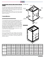
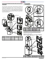
Model
Unit
Width
Depth
Height
a
b
c
d
14" Cabinet
in
14
18 3/4
27 1/8
13
14
16
12
mm
355.6
476.3
689
330.2
355.6
406.4
304.8
16" Cabinet
in
16
20 3/4
27 1/8
14
16
18
13
mm
406.4
527.1
689
355.6
406.4
457.2
330.2
18" Cabinet
in
18
25 3/4
29 1/8
16
20
23
14
mm
457.2
654.1
739.8
406.4
508
584.2
355.6
10
AIR CONDITIONING AND HEAT PUMPS USED WITH ZONING
SYSTEMS
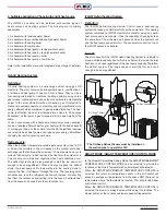
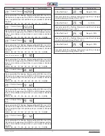
It is recommended that when zoning, air conditioning and heat pump
units used (with iFLOW air handler models iFLH-16000D, iFLH-
18000D and iFLH-18000Q with zoning) shall be variable speed
inverter type models. These units can ramp up or down in small
increments depending on the load.
Refer to Cooling Parameter Mode to set the blower speed
requirements for each zone and the minimum and maximum blower
speeds for cooling mode.
EXAMPLE ONLY
1) Location requirements and clearances:
• The installer shall comply with all local, state/provincial and national
code requirements that apply to the installation of this equipment.
• The air handler must be installed in such a way that electrical
components are protected from water during operation and service.
• If installed in an unconditioned space, sealant should be applied
around where the electrical wires, refrigerant tubing, and condensate
lines enter the cabinet. This appliance shall not be installed in a non-
conditioned space where the potential may exist for the appliance,
water lines and/or drain lines to freeze.
• If installed with air conditioning in a suspended application, ensure a
drain pan with a proper slope is installed.
Recommended Clearances:
Be sure to provide a minimum of 24” clearance to the front panel
of the iFLOW air handler. 0” clearance is allowed for all other sides
of the cabinet and for the first 36” of ductwork. Ensure adequate
clearance is left for the installation of ductwork, plumbing, and
electrical connections.
LEFT SIDE
0 inch
RIGHT SIDE
0 inch
BACK
0 inch
PLENUM
0 inch
BOTTOM
0 inch
FRONT
SERVICING
2) Dimensions
Installation
Содержание iFLH-14000W
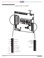
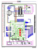
Страница 24: ...iFLOW HVAC INC www iflowhvac com SZ Field Installation Wiring Diagram 24 See Details Page 29...
Страница 26: ...iFLOW HVAC INC www iflowhvac com DZ Field Installation Wiring Diagram 26 See Details Page 29...
Страница 28: ...iFLOW HVAC INC www iflowhvac com QZ Field Installation Wiring Diagram 28...
Страница 30: ...iFLOW HVAC INC www iflowhvac com 4 Ladder Diagram 30...
Страница 34: ...iFLOW HVAC INC www iflowhvac com 34 3 Component Assembly Diagram and Parts Lists Assemble Diagram...
Страница 42: ...iFLOW HVAC INC www iflowhvac com 42 4 Installation Diagram iFLOW EZEE Plumbing Kit and iFLOW Stand...
Страница 43: ...iFLOW HVAC INC www iflowhvac com 43 Installation on the wall...
Страница 44: ...iFLOW HVAC INC www iflowhvac com 44...


