iFLOW HVAC INC.
www.iflowhvac.com
19
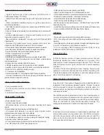
Item
Display
Range
Default
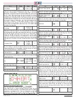
Coldest Indoor
‘Maximum Heating ON’
Temperature
60 ~ 80 °F
68˚F
Set a base temperature such that if the return air temperature
goes below that temperature (default is 68˚F), the unit will run at
maximum capacity. This temperature should be below any daytime
or nighttime ‘setback’.
Heat Source Type(s)
0, 1
0
0 : Hot Water Only (water heater, boiler or combi-boiler)
1: Hot Water + heat pump (Hybrid)
Outdoor Temperature for
‘H/P Heating OFF’
23 ~ 41˚F
(-5˚ ~ 5˚C)
32˚F
Set the lowest temperature at which you wish the heat pump
to operate (Balance Point Consideration: H/P COP and cost of
electricity at that temperature vs. gas efficiency and cost of gas).
Below that temperature, iFLOW will switch to the gas hot water
source.
‘Peak Rate Period 1 Start ’
- H/P Stop
00:00~24:00
07:00
Electricity Off-peak On time Set
‘Peak Rate Period 1
Finish’
- H/P Start
00:00~24:00
11:00
Use this function to start operating the heat pump again at end of
the ‘peak’ period 1 (started above).
‘Peak Rate Period 2 Start ’
- H/P Stop
00:00~24:00
19:00
If the electric utility has peak rates, use this function to stop operating
the heat pump at the beginning of the ‘peak’ period 2. (Refer to your
electric utility’s Time-of-Use Pricing and Schedule)
‘Peak Rate Period 2
Finish’
- H/P Start
00:00~24:00
21:00
Use this function to start operating the heat pump again at end of
the ‘peak’ period 2 (started above).
Zone 1 Blower Speed
(Heating Mode)
0 ~ 100 %
25%
Set the blower motor speed for zone 1 as a percentage of the
home’s total heat loss or CFM requirement. For example, if the
home’s total heat loss is 60MBH and Zone 1 accounts for 20MBH
(1/3) of that loss, the percentage would be 33%. If the home’s total
CFM requirement is 1200 CFM and Zone 1 accounts for 400 CFM
(1/3) of that loss, the percentage would be 33%.
Zone 2 Blower Speed
(Heating Mode)
0 ~100 %
25%
Set the blower motor speed for zone 2 as a percentage of the
home’s total heat loss or CFM requirement (see Zone 1 above for
details).
Item
Display
Range
Default
Zone 3 Blower Speed
(Heating Mode)
0 ~ 100 %
25%
Set the blower motor speed for zone 3 as a percentage of the
home’s total heat loss or CFM requirement (see Zone 1 above for
details).
Zone 4 Blower Speed
(Heating Mode)
0 ~ 100 %
25%
Set the blower motor speed for zone 4 as a percentage of the
home’s total heat loss or CFM requirement (see Zone 1 above for
details).
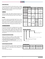
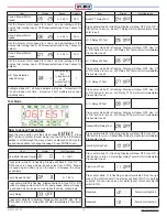
Cooling Parameter Mode
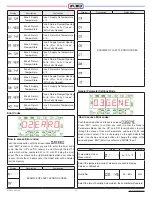
Push the mode button until the screen reads
Press ‘ENT’ (enter) to confirm Heating Parameter Mode. Use the
‘UP’ and ‘DN’ (down) buttons to scroll through the menu of heating
parameters, numbered 01-16. The 1-3 characters on the right
indicate the value. Use the up and down buttons to change the
range of the value and press ‘ENT’ to confirm and ‘MODE’ to exit.
Item
Display
Range
Default
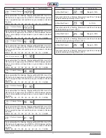
Minimum Blower Motor
Speed Setting
10 ~ 50 %
40 %
Used for advanced adjustment & troubleshooting only. Sets the
blower motor speed when a Y1 cooling call is received.
Maximum Blower Motor
Speed Setting
10 ~80%
70%
Used for advanced adjustment & troubleshooting only. Sets the
blower motor speed when a Y2 cooling call is received.
Blower OFF Delay Time
0 ~ 300 sec
60 Sec
Used for advanced adjustment & troubleshooting only. Sets a delay
of the blower motor shutting off after a call for cooling is completed.
To maximize efficiency, iFLOW continues to circulate the blower to
deliver any residual coil cooling to the home.
Zone 1 Blower Motor
Speed (Cooling Mode)
0 ~ 100 %
25%
Set the blower motor speed for zone 1 as a percentage of the
home’s total cooling load or CFM requirement. For example, if the
home’s total cooling load is 30MBH and Zone 1 accounts for 10MBH
(1/3) of that loss, the percentage would be 33%. If the home’s total
CFM requirement is 1200 CFM and Zone 1 accounts for 400 CFM
(1/3) of that loss, the percentage would be 33%.
How to access Cooling Parameter:
Содержание iFLH-14000W
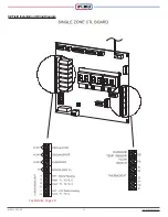
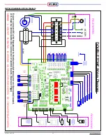
Страница 24: ...iFLOW HVAC INC www iflowhvac com SZ Field Installation Wiring Diagram 24 See Details Page 29...
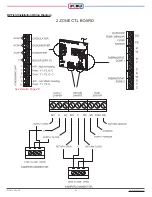
Страница 26: ...iFLOW HVAC INC www iflowhvac com DZ Field Installation Wiring Diagram 26 See Details Page 29...
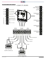
Страница 28: ...iFLOW HVAC INC www iflowhvac com QZ Field Installation Wiring Diagram 28...
Страница 30: ...iFLOW HVAC INC www iflowhvac com 4 Ladder Diagram 30...
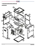
Страница 34: ...iFLOW HVAC INC www iflowhvac com 34 3 Component Assembly Diagram and Parts Lists Assemble Diagram...
Страница 42: ...iFLOW HVAC INC www iflowhvac com 42 4 Installation Diagram iFLOW EZEE Plumbing Kit and iFLOW Stand...
Страница 43: ...iFLOW HVAC INC www iflowhvac com 43 Installation on the wall...
Страница 44: ...iFLOW HVAC INC www iflowhvac com 44...

