


4
SRL Series
4
Operation
Chapter 3
OPERATION
3.1 Initial Inspection and Setup
This instrument was carefully inspected before ship-
ment. It should be in proper electrical and mechanical
order upon receipt.
An
OPERATION GUIDE
is attached to the case
of the instrument to provide ready reference to
specifi cations.
3.2 Connections
The SRL
series has three diff erent types of connec-
tions listed below.
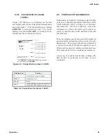
3.2.1 Connections for values
£
190 k
W
Values ≤190 kΩ have four insulated low thermal
emf binding posts for four-terminal measurements as
shown in Figure 3-1. The
fi fth binding post is con-
nected to the case. For high-resistance models (e.g.
>10
kΩ) two-terminal measurements may be made
by shorting
HI
to
HI
and
LO
to
LO
, preferably with
shorting links or other substantial means.
Figure 3-1: Connections for values
£
190 k
W
1
W
RESISTANCE STANDARD
MODEL SRL
-
1
Maximum Resistance Change (18°C to 28°C): ±3 ppm
Maximum Voltage: 0.5 V
Maximum Current: 0.5 A
LO
HI
LO
HI
SENSE
CURRENT
GND
HI INPUT
HI SENSE
LO INPUT
LO SENSE
GROUND
Binding Post
Function
CURRENT HI
Current input from source (e.g. ohmmeter)
CURRENT LO
Current return to source (e.g. ohmmeter)
SENSE HI
Measurement point for a four-wire ohmmeter
SENSE LO
Measurement point for a four-wire ohmmeter
GND
Guard or shield
Table 3-1: Connections for values
£
190 k
W
3.2.2 Connections for values
> 190 k
W
and <100 M
W
Values > 190 kΩ and <100 MΩ have two insulated,
low thermal emf binding posts for two-terminal mea-
surements as shown in Figure 3-2. The third binding
post is connected to the case.
Figure 3-2: Connections for values > 190 k
W
and <100 M
W
Binding Post
Function
HI
Input from source (e.g. ohmmeter)
SENSE LO
Measurement point
GND
Guard or shield
Table 3-2: Connections for values > 190 k
W
and <100 M
W
HI INPUT
HI SENSE
1 M
W
LO
HI
GND
RESISTANCE STANDARD
MODEL SRL
-
1M
Maximum Resistance Change (18°C to 28°C):
±
2 ppm
Maximum Voltage: 100 V
Maximum Current: 0.1 mA
LO SENSE
LO INPUT
GROUND
Содержание SRL Series
Страница 17: ......


