WSB-9154 CPU Card
Page 76
Step 2:
Align the DIMM with the socket
. The DIMM must be oriented in such a way
that the notch in the middle of the DIMM must be aligned with the plastic bridge
in the socket. See
Figure 5-7
.
Step 3:
Insert the DIMM
. Once properly aligned, the DIMM can be inserted into the
socket. As the DIMM is inserted, the white handles on the side of the socket will
close automatically and secure the DIMM to the socket. See
Figure 5-7
.
Step 4:
Removing a DIMM
. To remove a DIMM, push both handles outward. The
memory module is ejected by a mechanism in the socket.
Step 0:
5.4 Jumper Settings
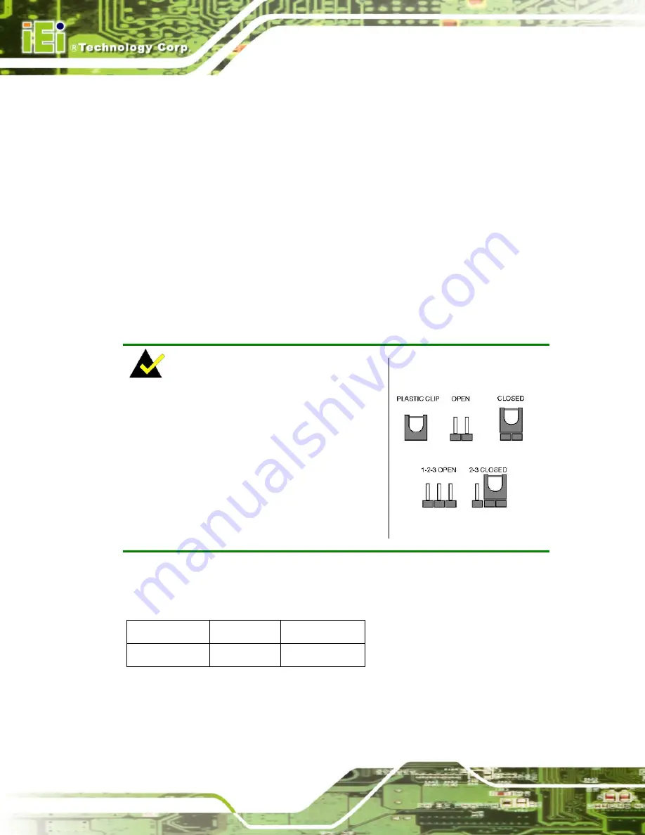
NOTE:
A jumper is a metal bridge used to close an
electrical circuit. It consists of two or three metal
pins and a small metal clip (often protected by a
plastic cover) that slides over the pins to connect
them. To CLOSE/SHORT a jumper means
connecting the pins of the jumper with the plastic
clip and to OPEN a jumper means removing the
plastic clip from a jumper.
Figure 5-8: Jumpers
Before the WSB-9154 is installed in the system, the jumpers must be set in accordance
with the desired configuration. The jumpers on the WSB-9154 are listed in
Table 5-1
.
Description Label
Type
Clear CMOS
J_CMOS1
3-pin header
Table 5-1: Jumpers
Содержание WSB-9154
Страница 1: ...WSB 9154 CPU Card Page i...
Страница 19: ...WSB 9154 CPU Card Page 1 1 Introduction Chapter 1...
Страница 24: ...WSB 9154 CPU Card Page 6 THIS PAGE IS INTENTIONALLY LEFT BLANK...
Страница 25: ...WSB 9154 CPU Card Page 7 2 Detailed Specifications Chapter 2...
Страница 49: ...WSB 9154 CPU Card Page 31 3 Unpacking Chapter 3...
Страница 54: ...WSB 9154 CPU Card Page 36 THIS PAGE IS INTENTIONALLY LEFT BLANK...
Страница 55: ...WSB 9154 CPU Card Page 37 4 Connector Pinouts Chapter 4...
Страница 69: ...WSB 9154 CPU Card Page 51 Figure 4 10 IDE Device Connector Locations...
Страница 82: ...WSB 9154 CPU Card Page 64 THIS PAGE IS INTENTIONALLY LEFT BLANK...
Страница 83: ...WSB 9154 CPU Card Page 65 5 Installation Chapter 5...
Страница 116: ...WSB 9154 CPU Card Page 98 THIS PAGE IS INTENTIONALLY LEFT BLANK...
Страница 117: ...WSB 9154 CPU Card Page 99 6 AMI BIOS Chapter 6...
Страница 149: ...WSB 9154 CPU Card Page 131 6 5 Boot Use the Boot menu BIOS Menu 15 to configure system boot options BIOS Menu 15 Boot...
Страница 168: ...WSB 9154 CPU Card Page 150 THIS PAGE IS INTENTIONALLY LEFT BLANK...
Страница 169: ...WSB 9154 CPU Card Page 151 7 Driver Installation Chapter 7...
Страница 181: ...WSB 9154 CPU Card Page 163 Figure 7 17 System Icon Step 3 Click the Device Manager tab Figure 7 18...
Страница 182: ...WSB 9154 CPU Card Page 164 Figure 7 18 Device Manager Tab Step 4 A list of system hardware devices appears Figure 7 19...
Страница 198: ...WSB 9154 CPU Card Page 180 Figure 7 41 Access Windows Control Panel...
Страница 199: ...WSB 9154 CPU Card Page 181 Step 2 Double click the System icon Figure 7 42 Figure 7 42 Double Click the System Icon...
Страница 204: ...WSB 9154 CPU Card Page 186 THIS PAGE IS INTENTIONALLY LEFT BLANK...
Страница 205: ...WSB 9154 CPU Card Page 187 A BIOS Menu Options Appendix A...
Страница 209: ...WSB 9154 CPU Card Page 191 B Watchdog Timer Appendix B...
Страница 212: ...WSB 9154 CPU Card Page 194 THIS PAGE IS INTENTIONALLY LEFT BLANK...
Страница 213: ...WSB 9154 CPU Card Page 195 C Address Mapping Appendix C...
Страница 216: ...WSB 9154 CPU Card Page 198 THIS PAGE IS INTENTIONALLY LEFT BLANK...
Страница 217: ...WSB 9154 CPU Card Page 199 D DIO Interface Appendix D...
Страница 220: ...WSB 9154 CPU Card Page 202 THIS PAGE IS INTENTIONALLY LEFT BLANK...
Страница 221: ...WSB 9154 CPU Card Page 203 Index...


