background image


ECN-780-Q67  Em b e d d e d   S ys te m  

P a g e   32 


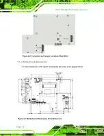
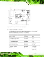
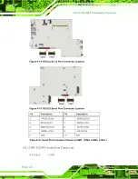
Figure 4-2: Connector and Jumper Locations (Rear Side) 

4.1.2


Mo th e rb o a rd   Dim e n s io n s  

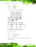
The main dimensions of the system motherboard are shown in the diagram below. 


Figure 4-3: Motherboard Dimensions (Front Side) (mm) 

Содержание ECN-780-Q67

Страница 1: ...Page i IEI Technology Corp Us er Manual MODEL ECN 780 Q67 Embedded Sys tem with 2nd Gen Intel Core i7 i5 i3 Des ktop Proces s ors DVI HDMI VGA GbE Two USB 3 0 Two USB 2 0 Three COM and RoHS Compliant...

Страница 2: ...mbedded Sys tem Page ii Revis ion Date Version Changes 12 September 2012 1 02 Update the pictures of rear panel and front panel 6 June 2012 1 01 Update the pictures of rear panel 6 April 2012 1 00 Ini...

Страница 3: ...ages arising out of the use or inability to use the product or documentation even if advised of the possibility of such damages This document contains proprietary information protected by copyright Al...

Страница 4: ...INSTALLATION PRECAUTIONS 13 3 2 INSTALLATION AND CONFIGURATION STEPS 13 3 3 HARD DISK DRIVE HDD INSTALLATION 13 3 4 AT ATX MODE SELECTION 15 3 4 1 AT Power Mode 16 3 4 2 ATX Power Mode 16 3 5 RESET T...

Страница 5: ...gramming Connector 37 4 2 5 Fan Connector System 38 4 2 6 Keyboard Mouse Connector 39 4 2 7 LED Module Connector 40 4 2 8 PCIe Mini Card Slot 41 4 2 9 Power Connector 42 4 2 10 RS 232 Serial Port Conn...

Страница 6: ...figuration 67 5 3 7 USB Configuration 68 5 3 8 F81866 Super IO Configuration 69 5 3 8 1 Serial Port n Configuration 70 5 3 9 F81866 H W Monitor 74 5 3 9 1 Smart Fan Mode Configuration 76 5 3 10 Serial...

Страница 7: ...IOS MENU OPTIONS 121 C ONE KEY RECOVERY 124 C 1 ONE KEY RECOVERY INTRODUCTION 125 C 1 1 System Requirement 126 C 1 2 Supported Operating System 127 C 2 SETUP PROCEDURE FOR WINDOWS 128 C 2 1 Hardware a...

Страница 8: ...Shared Directory 158 C 6 6 Setup a Client System for Auto Recovery 159 C 7 OTHER INFORMATION 162 C 7 1 Using AHCI Mode or ALi M5283 VIA VT6421A Controller 162 C 7 2 System Memory Requirement 164 D WA...

Страница 9: ...el 21 Figure 3 10 Peripheral Connectors Rear Panel 21 Figure 3 11 Audio Connector 22 Figure 3 12 DVI Connector 23 Figure 3 13 HDMI Connection 24 Figure 3 14 LAN Connection 25 Figure 3 15 DB 9 Serial P...

Страница 10: ...Figure 4 25 Clear CMOS Jumper Location 54 Figure 4 26 Flash Descriptor Security Override Jumper Location 55 Figure 6 1 Drivers 95 Figure 6 2 Chipset Driver Screen 96 Figure 6 3 Chipset Driver Welcome...

Страница 11: ...Screen 115 Figure C 1 IEI One Key Recovery Tool Menu 125 Figure C 2 Launching the Recovery Tool 130 Figure C 3 Recovery Tool Setup Menu 130 Figure C 4 Command Prompt 131 Figure C 5 Partition Creation...

Страница 12: ...8 Press any key to continue 144 Figure C 29 Partitions for Linux 146 Figure C 30 Manual Recovery Environment for Linux 147 Figure C 31 Access menu lst in Linux Text Mode 148 Figure C 32 Recovery Tool...

Страница 13: ...rd Mouse Connector Pinouts 40 Table 4 8 LED Module Connector Pinouts 41 Table 4 9 Power Connector Pinouts 43 Table 4 10 Serial Port Connector Pinouts COM1 COM2 COM3 COM4 44 Table 4 11 RS 422 485 Seria...

Страница 14: ...ECN 780 Q67 Embedded Sys tem Page 1 Chapter 1 1 Introduction...

Страница 15: ...Q67 supports a 2 5 SATA HDD with up to 3 Gb s data transfer rate Three serial ports two external USB 2 0 ports and two external USB 3 0 ports ensure simplified connectivity to a variety of external pe...

Страница 16: ...speed data transfer 1 4 Technical Specifications The ECN 780 Q67 technical specifications are listed in Table 1 2 Chas s is Color Black Dimens ions 230 x 60 x 173 mm Chas s is Cons truction SECC Moth...

Страница 17: ...n rear Interior Expans ions 2 x PCIe Mini slot reserved for Wi Fi and TV Tunner Switch Reset switch AT ATX switch Watchdog Timer Software programmable support 1 255 sec system reset Power Power Supply...

Страница 18: ...CN 780 Q67 has the following features Figure 1 2 1 x HDD LED 1 x Power button 1 x Power LED 1 x RS 232 DB 9 connector COM3 1 x RS 422 485 DB 9 connector COM5 2 x USB 2 0 connectors Figure 1 2 ECN 780...

Страница 19: ...e 6 1 x RS 232 DB 9 connector COM1 1 x DVI D port 1 x HDMI port 1 x Reset button 2 x RJ 45 LAN connectors 1 x TV Tuner antenna reserved 2 x USB 3 0 connectors 1 x VGA port 1 x Wi Fi antenna reserved F...

Страница 20: ...ECN 780 Q67 Embedded Sys tem Page 7 1 7 Dimens ions The physical dimensions are shown below Figure 1 4 Physical Dimensions mm...

Страница 21: ...ECN 780 Q67 Embedded Sys tem Page 8 Chapter 2 2 Unpacking...

Страница 22: ...c wristband Wearing a simple anti static wristband can help to prevent ESD from damaging the board Self grounding Before handling the board touch any grounded conducting material During the time the b...

Страница 23: ...tact an IEI sales representative directly To contact an IEI sales representative please send an email to sales iei com tw The ECN 780 Q67 is shipped with the following components Quantity Item and Par...

Страница 24: ...ECN 780 Q67 Embedded Sys tem Page 11 Quantity Item and Part Number Image 1 Thermal pad P N 34100 000197 RS 1 Utility CD 1 One Key Recovery CD Table 2 1 Package List Contents...

Страница 25: ...ECN 780 Q67 Embedded Sys tem Page 12 Chapter 3 3 Ins tallation...

Страница 26: ...ted only by trained and qualified personnel Maintenance upgrades or repairs may only be carried out by qualified personnel who are familiar with the associated dangers Grounding The ECN 780 Q67 should...

Страница 27: ...ECN 780 Q67 Embedded Sys tem Page 14 Figure 3 1 Retention Screws Removal Step 2 Open the HDD cover and locate the HDD bracket Figure 3 2 Figure 3 2 HDD Bracket...

Страница 28: ...re 3 3 Figure 3 3 HDD Retention Screws Step 4 Replace the HDD cover and secure it using five 5 previously removed retention screws 3 4 AT ATX Mode Selection AT or ATX power mode can be used on the ECN...

Страница 29: ...central management center and other applications including ATM Self service kiosk Plant environment monitoring system Factory automation platform Manufacturing shop flow 3 4 2 ATX Power Mode With the...

Страница 30: ...ar panel Figure 3 5 Figure 3 5 Reset Button Location Step 2 Press the reset button Step 0 3 6 Powering On Off the Sys tem To power on the system follow the steps below Step 1 Press the power button on...

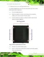
Страница 31: ...age 18 Figure 3 6 Power Button Location 3 7 Mount the Sys tem The ECN 780 Q67 supports wall mounting The bottom panel of the ECN 780 Q67 contains four screw holes for mounting Figure 3 7 the system Fi...

Страница 32: ...two retention screw holes in each bracket with the corresponding retention screw holes on the sides of the bottom surface Step 3 Secure the brackets to the system by inserting two retention screws in...

Страница 33: ...8 External Peripheral Interface Connectors The following external peripheral devices can be connected to the external peripheral interface connectors Audio devices DVI devices HDMI devices RJ 45 Ethe...

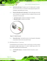
Страница 34: ...al Connectors Front Panel Figure 3 10 Peripheral Connectors Rear Panel 3 8 1 Audio Connection The audio jacks on the external audio connector enable the ECN 780 Q67 to be connected to a stereo sound s...

Страница 35: ...o the audio jacks Line Out port Lime Connects to a headphone or a speaker Microphone Pink Connects to a microphone Figure 3 11 Audio Connector Step 3 Check audio clarity Check that the sound is coming...

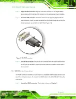
Страница 36: ...ice into the female connector on the ECN 780 Q67 See Figure 3 12 Figure 3 12 DVI Connector Step 4 Secure the connector Secure the DVI connector from the digital display device to the external interfac...

Страница 37: ...again that the connector is aligned correctly and that the connector is being inserted with the right way up 3 8 4 LAN Connection There are two external RJ 45 LAN connectors The RJ 45 connector enable...

Страница 38: ...ere are two RS 232 DB 9 connectors and one RS 422 485 connector of the ECN 780 Q67 for serial device connection Follow the steps below to connect a serial device to the DB 9 connector of the ECN 780 Q...

Страница 39: ...e connector Step 0 3 8 6 USB Device Connection NOTE User must install the USB 3 0 driver before connecting a USB device to the system or else the system may not recognize the connected device There ar...

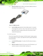
Страница 40: ...tep 0 3 8 7 VGA Monitor Connection The ECN 780 Q67 has a single female DB 15 connector on the external peripheral interface panel The DB 15 connector is connected to a CRT or VGA monitor To connect a...

Страница 41: ...rom the VGA monitor to the external interface by tightening the two retention screws on either side of the connector 3 9 Intel AMT Setup Procedure The ECN 780 Q67 is featured with the Intel Active Man...

Страница 42: ...S extension MEBx To get into the Intel MEBx settings press Ctrl P after a single beep during boot up process Enter the Intel current ME password as it requires the Intel default password is admin NOTE...

Страница 43: ...ECN 780 Q67 Embedded Sys tem Page 30 Chapter 4 4 Sys tem Motherboard...

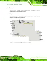
Страница 44: ...therboard comes with a number of peripheral interface connectors and configuration jumpers 4 1 1 Layout The connector locations are shown in Figure 4 1 The connector pinouts for these connectors are l...

Страница 45: ...ys tem Page 32 Figure 4 2 Connector and Jumper Locations Rear Side 4 1 2 Motherboard Dimens ions The main dimensions of the system motherboard are shown in the diagram below Figure 4 3 Motherboard Dim...

Страница 46: ...iptions of these connectors can be found below Connector Type Label Battery connector 2 pin wafer BAT1 BIOS programming connector 6 pin wafer JSPI1 Digital I O connector 10 pin header DIO1 EC programm...

Страница 47: ...1 USB 2 0 connectors 8 pin header USB2_3 USB4_5 VGA connector 10 pin header VGA1 Table 4 1 Peripheral Interface Connectors 4 2 Internal Peripheral Connectors Internal peripheral connectors are found o...

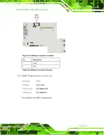
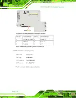
Страница 48: ...ttery Connector Location Pin Description 1 VBATT 2 GND Table 4 2 Battery Connector Pinouts 4 2 2 BIOS Programming Connector CN Label J SPI1 CN Type 6 pin wafer CN Location See Figure 4 6 CN Pinouts Se...

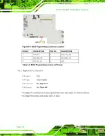
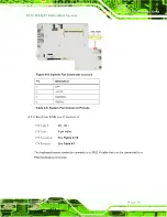
Страница 49: ...3 SPI_SO0_CN 4 SPI_CLK0_CN 5 SPI_SI0_CN 6 GND Table 4 3 BIOS Programming Connector Pinouts 4 2 3 Digital I O Connector CN Label DIO1 CN Type 10 pin header CN Location See Figure 4 7 CN Pinouts See Tab...

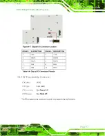
Страница 50: ...SCRIPTION 1 V5S 2 V5S 3 DOUT4 4 DOUT3 5 DOUT2 6 DOUT1 7 DIN4 8 DIN3 9 DIN2 10 DIN1 Table 4 4 Digital I O Connector Pinouts 4 2 4 EC Programming Connector CN Label J SPI2 CN Type 6 pin wafer CN Locatio...

Страница 51: ...RIPTION PIN NO DESCRIPTION 1 V3 3A_EC_CONN 2 FSCE _S 3 FMISO_S 4 FSCK_S 5 FMOSI_S 6 GND Table 4 5 EC Programming Connector Pinouts 4 2 5 Fan Connector Sys tem CN Label SYS_FAN1 CN Type 4 pin wafer CN...

Страница 52: ...GND 2 V12S 3 FANPWM1 4 FANIN1 Table 4 6 System Fan Connector Pinouts 4 2 6 Keyboard Mous e Connector CN Label KB_MS1 CN Type 6 pin wafer CN Location See Figure 4 10 CN Pinouts See Table 4 7 The keyboa...

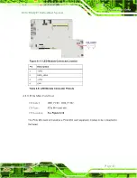
Страница 53: ..._KBMS 2 MSDATA 3 MSCLK 4 KBDATA 5 KBCLK 6 GND Table 4 7 Keyboard Mouse Connector Pinouts 4 2 7 LED Module Connector CN Label LED_CONN1 CN Type 4 pin wafer CN Location See Figure 4 11 CN Pinouts See Ta...

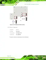
Страница 54: ...scription 1 V5S 2 SATA_LED 3 V5A 4 GND Table 4 8 LED Module Connector Pinouts 4 2 8 PCIe Mini Card Slot CN Label MINI_PCIE1 MINI_PCIE2 CN Type PCIe Mini card slot CN Location See Figure 4 12 The PCIe...

Страница 55: ...Sys tem Page 42 Figure 4 12 PCIe Mini Card Slot Location 4 2 9 Power Connector CN Label DC_IN1 CN Type 2 pin wafer CN Location See Figure 4 13 CN Pinouts See Table 4 9 The power connector provides pow...

Страница 56: ...ctor Pinouts 4 2 10 RS 232 Serial Port Connectors CN Label COM1 COM2 COM3 COM4 CN Type 10 pin header CN Location See Figure 4 14 and Figure 4 15 CN Pinouts See Table 4 10 The 10 pin serial port connec...

Страница 57: ...2 Serial Port Connector Location Pin Description Pin Description 1 NDCD1 2 3 4 6 NDSR1 2 3 4 2 NSIN1 2 3 4 7 NRTS1 2 3 4 3 NSOUT1 2 3 4 8 NCTS1 2 3 4 4 NDTR1 2 3 4 9 XRI1 2 3 4 5 GND 10 N A Table 4 10...

Страница 58: ...ial Port Connector Location Pin Description Pin Description 1 RXD485 2 N A 3 RXD485 4 N A 5 TXD485 6 N A 7 TXD485 8 N A Table 4 11 RS 422 485 Serial Port Connector Pinouts 4 2 12 SATA Drive Connectors...

Страница 59: ...Figure 4 17 SATA Drive Connector Locations 4 2 13 SATA Power Connectors CN Label CN1 CN2 CN Type 2 pin wafer CN Location See Figure 4 18 CN Pinouts See Table 4 12 Use the SATA Power Connector to conn...

Страница 60: ...ns Pin Description 1 V5S 2 GND Table 4 12 SATA Power Connector Pinouts 4 2 14 SMBus Connector CN Label SMBUS1 CN Type 4 pin wafer CN Location See Figure 4 19 CN Pinouts See Table 4 13 The SMBus System...

Страница 61: ...ctor Location Pin Description 1 GND 2 SMB_DATA 3 SMB_CLK_A 4 V5S Table 4 13 SMBus Connector Pinouts 4 2 15 SO DIMM Connector CN Label SO DIMM1 CN Type 204 pin DDR3 SO DIMM slot CN Location See Figure...

Страница 62: ...ocations 4 2 16 K Type Thermocouple Connectors CN Label CN4 CN5 CN Type 2 pin wafer CN Location See Figure 4 21 CN Pinouts See Table 4 14 The K type thermocouple connector connects to the K type therm...

Страница 63: ...Label TPM1 CN Type 20 pin header CN Location See Figure 4 22 CN Pinouts See Table 4 15 The TPM connector connects to a TPM module Figure 4 22 TPM Connector Location PIN NO DESCRIPTION PIN NO DESCRIPT...

Страница 64: ...Q 0 Table 4 15 TPM Connector Pinouts 4 2 18 USB 2 0 Connectors CN Label USB2_3 USB4_5 CN Type 8 pin header CN Location See Figure 4 23 CN Pinouts See Table 4 16 The USB header can connect to two USB d...

Страница 65: ...A1 CN Type 10 pin header CN Location See Figure 4 24 CN Pinouts See Table 4 17 The VGA connector connects to a monitor Figure 4 24 VGA Connector Location Pin Description Pin Description 1 CRT_RED 2 CR...

Страница 66: ...on the ECN 780 Q67 are listed in Table 4 18 Des cription Label Type Clear CMOS J_CMOS2 3 pin header Flash descriptor security override J_FLASH1 3 pin header Table 4 18 Jumpers 4 3 1 Clear CMOS J umper...

Страница 67: ...n 4 3 2 Flas h Des criptor Security Override J umper Label J _FLASH1 J umper Type 3 pin header J umper Settings See Table 4 20 J umper Location See Figure 4 26 The Flash Descriptor Security Override j...

Страница 68: ...ECN 780 Q67 Embedded Sys tem Page 55 Figure 4 26 Flash Descriptor Security Override Jumper Location...

Страница 69: ...ECN 780 Q67 Embedded Sys tem Page 56 Chapter 5 5 BIOS...

Страница 70: ...efore the DELETE key is pressed restart the computer and try again 5 1 2 Us ing Setup Use the arrow keys to highlight items press ENTER to select use the PageUp and PageDown keys to change entries pre...

Страница 71: ...t after changes to the system configuration is made CMOS defaults Use the jumper described in Chapter 5 5 1 5 BIOS Menu Bar The menu bar on top of the BIOS screen has the following main items Main Cha...

Страница 72: ...2012 System Time 14 20 27 Access Level Administrator Set the Time Use Tab to switch between Time elements Select Screen Select Item EnterSelect F1 General Help F2 Previous Values F3 Optimized Default...

Страница 73: ...m Overview field also has two user configurable fields Sys tem Date xx xx xx Use the System Date option to set the system date Manually enter the day month and year Sys tem Time xx xx xx Use the Syste...

Страница 74: ...neral Help F2 Previous Values F3 Optimized Defaults F4 Save ESC Exit Version 2 00 1201 Copyright C 2009 American Megatrends Inc BIOS Menu 2 Advanced 5 3 1 ACPI Configuration The ACPI Configuration men...

Страница 75: ...king state but more power is saved 5 3 2 RTC Wake Settings The RTC Wake Settings menu BIOS Menu 4 configures RTC wake event Aptio Setup Utility Copyright C 2011 American Megatrends Inc Advanced Wake s...

Страница 76: ...ate when the alarm goes off 5 3 3 Trus ted Computing Use the Trusted Computing menu BIOS Menu 5 to configure settings related to the Trusted Computing Group TCG Trusted Platform Module TPM Aptio Setup...

Страница 77: ...Inc Advanced CPU Configuration CPU Information Hyper threading Enabled Intel Virtualization Technology Enabled Socket specific CPU Information Select Screen Select Item EnterSelect Change Opt F1 Gene...

Страница 78: ...100T CPU 2 50GHz CPU Signature 206a7 Microcode Patch 1b Max CPU Speed 2500 MHz Min CPU Speed 1600 MHz Processor Cores 2 Intel HT Technology Supported Intel VT x Technology Supported Intel SMX Technolo...

Страница 79: ...torage space on the L3 cache 5 3 5 SATA Configuration Use the SATA Configuration menu BIOS Menu 8 to change and or set the configuration of the SATA devices installed in the system Aptio Setup Utility...

Страница 80: ...his mode a SATA channel will replace one of the IDE channels 5 3 6 Intel TXT LT Configuration Use the Intel TXT LT Configuration menu BIOS Menu 9 to configure Intel Trusted Execution Technology suppor...

Страница 81: ...lp F2 Previous Values F3 Optimized Defaults F4 Save ESC Exit Version 2 00 1201 Copyright C 2009 American Megatrends Inc BIOS Menu 10 USB Configuration USB Devices The USB Devices Enabled field lists t...

Страница 82: ...al ports Aptio Setup Utility Copyright C 2009 American Megatrends Inc Advanced F81866 Super IO Configuration F81866 Super IO Chip F81866 Serial Port 1 Configuration Serial Port 2 Configuration Serial...

Страница 83: ...F3 Optimized Defaults F4 Save ESC Exit Version 2 00 1201 Copyright C 2009 American Megatrends Inc BIOS Menu 12 Serial Port n Configuration Menu 5 3 8 1 1 Serial Port 1 Configuration Serial Port Enabl...

Страница 84: ...ion to enable or disable the serial port Disabled Disable the serial port Enabled DEFAULT Enable the serial port Change Settings Auto Use the Change Settings option to change the serial port IO port a...

Страница 85: ...ial port IO port address and interrupt address Auto DEFAULT The serial port IO port address and interrupt address are automatically detected IO 3E8h IRQ 7 Serial Port I O port address is 3E8h and the...

Страница 86: ...atically detected IO 2E8h IRQ 10 Serial Port I O port address is 2E8h and the interrupt address is IRQ10 IO 3F8h IRQ 7 10 Serial Port I O port address is 3F8h and the interrupt address is IRQ7 10 IO 2...

Страница 87: ...IRQ 10 11 Serial Port I O port address is 2C0h and the interrupt address is IRQ10 11 IO 2C8h IRQ 10 11 Serial Port I O port address is 2C8h and the interrupt address is IRQ10 11 IO 3E8h IRQ 10 11 Ser...

Страница 88: ...V VSB5V 5 088 V VCC3V 3 296 V VSB3V 3 312 V VBAT 3 248 V Smart Fan Mode Select Select Screen Select Item EnterSelect F1 General Help F2 Previous Values F3 Optimized Defaults F4 Save ESC Exit Version...

Страница 89: ...art Fan control settings Select Screen Select Item EnterSelect F1 General Help F2 Previous Values F3 Optimized Defaults F4 Save ESC Exit Version 2 00 1201 Copyright C 2009 American Megatrends Inc BIOS...

Страница 90: ...ion and enter a decimal number between 0 and 127 The temperature range is specified below Minimum Value 0 C Maximum Value 127 C Temperature of Off 80 WARNING Setting this value too high may cause the...

Страница 91: ...Slope Duty Cycle option can only be set if the CPU Smart Fan control option is set to Auto Mode Use the Slope Duty Cycle option to select the linear rate at which the PWM mode increases with respect t...

Страница 92: ...ect Item EnterSelect F1 General Help F2 Previous Values F3 Optimized Defaults F4 Save ESC Exit Version 2 00 1201 Copyright C 2009 American Megatrends Inc BIOS Menu 15 Serial Port Console Redirection C...

Страница 93: ...eneral Help F2 Previous Values F3 Optimized Defaults F4 Save ESC Exit Version 2 00 1201 Copyright C 2009 American Megatrends Inc BIOS Menu 16 Console Redirection Settings Terminal Type ANSI Use the Te...

Страница 94: ...recover system automatically within 10 min when OS crashes Please install Auto Recovery API service before enabling this function Select Screen Select Item EnterSelect Change Opt F1 General Help F2 Pr...

Страница 95: ...S menu may cause the system to malfunction Aptio Setup Utility Copyright C 2009 American Megatrends Inc Main Advanced Chipset Boot Security Save Exit North Bridge South Bridge Intel IGD SWSCI OpRegion...

Страница 96: ...Select Item EnterSelect F1 General Help F2 Previous Values F3 Optimized Defaults F4 Save ESC Exit Version 2 00 1201 Copyright C 2009 American Megatrends Inc BIOS Menu 19 Northbridge Chipset Configura...

Страница 97: ...abled Azalia internal HDMI codec Enabled Power Saving Function Disabled WIFI Function Enabled Enabled Disabled Azalia HD Audio Select Screen Select Item EnterSelect F1 General Help F2 Previous Values...

Страница 98: ...c for High Definition Audio Disabled Disables the internal HDMI codec for High Definition Audio Enabled DEFAULT Enables the internal HDMI codec for High Definition Audio Power Saving Function Dis able...

Страница 99: ...elp F2 Previous Values F3 Optimized Defaults F4 Save ESC Exit Version 2 00 1201 Copyright C 2009 American Megatrends Inc BIOS Menu 21 Intel IGD SWSCI OpRegion DVMT Mode Select DVMT Mode Use the DVMT M...

Страница 100: ...the Intel Management Engine ME configuration options Aptio Setup Utility Copyright C 2011 American Megatrends Inc Chipset Intel ME Subsystem Configuration ME Version 7 0 10 1203 MEBx Mode Normal Uncon...

Страница 101: ...2009 American Megatrends Inc Main Advanced Chipset Boot Security Save Exit Boot Configuration Bootup NumLock State On Quiet Boot Enabled Option ROM Messages Force BIOS Intel Lan PXE Boot Disabled Boo...

Страница 102: ...LED light on the keyboard is lit Quiet Boot Enabled Use the Quiet Boot BIOS option to select the screen display when the system boots Disabled Normal POST messages displayed Enabled DEFAULT OEM Logo...

Страница 103: ...d Description If ONLY the Administrator s password is set then this only limits access to Setup and is only asked for when entering Setup If ONLY the User s password is set then this is a power on pas...

Страница 104: ...t Item EnterSelect F1 General Help F2 Previous Values F3 Optimized Defaults F4 Save ESC Exit Version 2 00 1201 Copyright C 2009 American Megatrends Inc BIOS Menu 25 Exit Save Changes and Exit Use the...

Страница 105: ...age 92 Save as Us er Defaults Use the Save as User Defaults option to save the changes done so far as user defaults Res tore Us er Defaults Use the Restore User Defaults option to restore the user def...

Страница 106: ...ECN 780 Q67 Embedded Sys tem Page 93 6 Software Drivers Chapter 5...

Страница 107: ...rt for the latest updates The following drivers can be installed on the system Chipset VGA LAN Audio USB 3 0 SA46_ME_SW_IS Installation instructions are given below 6 2 Starting the Driver Program To...

Страница 108: ...hips et Driver Ins tallation To install the chipset driver please do the following Step 1 Access the driver list See Section 6 2 Step 2 Click Chipset Step 3 Locate the setup file and double click on i...

Страница 109: ...6 2 Chipset Driver Screen Step 5 When the setup files are completely extracted the Welcome Screen in Figure 6 3 appears Step 6 Click Next to continue Figure 6 3 Chipset Driver Welcome Screen Step 7 T...

Страница 110: ...Embedded Sys tem Page 97 Step 8 Read the License Agreement Step 9 Click Yes to continue Figure 6 4 Chipset Driver License Agreement Step 10 The Read Me file in Figure 6 5 appears Step 11 Click Next t...

Страница 111: ...hipset Driver Read Me File Step 12 Setup Operations are performed as shown in Figure 6 6 Step 13 Once the Setup Operations are complete click Next to continue Figure 6 6 Chipset Driver Setup Operation...

Страница 112: ...lation Finish Screen 6 4 Graphics Driver Ins tallation To install the Graphics driver please do the following Step 1 Access the driver list See Section 6 2 Step 2 Click VGA and select the folder which...

Страница 113: ...8 Graphics Driver Read Me File Step 6 The installation files are extracted See Figure 6 9 Step 7 Click Next to continue Figure 6 9 Graphics Driver Setup Files Extracted Step 8 The Welcome Screen in Fi...

Страница 114: ...s Driver Welcome Screen Step 10 The License Agreement in Figure 6 11 appears Step 11 Click Yes to accept the agreement and continue Figure 6 11 Graphics Driver License Agreement Step 12 The Read Me fi...

Страница 115: ...Operations are performed as shown in Figure 6 13 Step 15 Once the Setup Operations are complete click Next to continue Figure 6 13 Graphics Driver Setup Operations Step 16 The Finish Screen in Figure...

Страница 116: ...LAN Driver Ins tallation To install the LAN driver please do the following Step 1 Access the driver list See Section 6 2 Step 2 Click LAN Step 3 Locate the Autorun file and double click it Step 4 The...

Страница 117: ...nection Menu Step 6 The Welcome screen in Figure 6 16 appears Figure 6 16 LAN Driver Welcome Screen Step 7 Click Next to continue Step 8 The License Agreement in Figure 6 17 appears Step 9 Accept the...

Страница 118: ...Step 10 Click Next to continue Figure 6 17 LAN Driver License Agreement Step 11 The Setup Options screen in Figure 6 18 appears Step 12 Select program features to install Step 13 Click Next to continu...

Страница 119: ...19 appears Step 15 Click Install to proceed with the installation Figure 6 19 LAN Driver Installation Step 16 The program begins to install Step 17 When the driver installation is complete the screen...

Страница 120: ...driver list See Section 6 2 Step 2 Click Audio and select the folder which corresponds to your operating system Step 3 Double click the setup file Step 4 The Audio Driver Welcome Screen in Figure 6 21...

Страница 121: ...Figure 6 22 Audio Driver Installation Step 7 When the installation is complete the screen in Figure 6 23 appears Step 8 Select Yes I want to restart my computer now and click Finish Step 0 Figure 6 2...

Страница 122: ...Section 6 2 Step 2 Click USB 3 0 and select the folder which corresponds to your operating system Step 3 Double click the setup file Step 4 The Welcome Screen in Figure 6 24 appears Step 5 Click Next...

Страница 123: ...Embedded Sys tem Page 110 Figure 6 25 USB 3 0 Driver Choose Install Location Step 8 The program is ready to install Figure 6 26 Step 9 Click INSTALL to continue Figure 6 26 USB 3 0 Driver Choose Insta...

Страница 124: ...el ME components includes Intel Management Engine Interface Intel ME Interface Serial Over LAN SOL driver Local Manageability Service LMS User Notification Service UNS Intel Management and Security St...

Страница 125: ...d Sys tem Page 112 6 28 appears Step 5 Click Next to continue Figure 6 28 Intel ME Driver Welcome Screen Step 6 The license agreement in Figure 6 29 appears Step 7 Read the License Agreement Step 8 Cl...

Страница 126: ...CN 780 Q67 Embedded Sys tem Page 113 Figure 6 29 Intel ME Driver License Agreement Step 9 The Read Me file in Figure 6 30 appears Step 10 Click Next to continue Figure 6 30 Intel ME Driver Read Me Fil...

Страница 127: ...rmed as shown in Figure 6 31 Step 12 Once the Setup Operations are complete click Next to continue Figure 6 31 Intel ME Driver Setup Operations Step 13 The Finish screen in Figure 6 32 appears Step 14...

Страница 128: ...ECN 780 Q67 Embedded Sys tem Page 115 Figure 6 32 Intel ME Driver Installation Finish Screen...

Страница 129: ...ECN 780 Q67 Embedded Sys tem Page 116 A Safety Precautions Appendix A...

Страница 130: ...e power is turned off and the power cord is disconnected whenever the ECN 780 Q67 is being installed moved or modified Do not apply voltage levels that exceed the specified voltage range Doing so may...

Страница 131: ...following anti static precautions are strictly adhered to Wear an anti static wristband Wearing a simple anti static wristband can help to prevent ESD from damaging any electrical component Self grou...

Страница 132: ...ctrical and electronic products carrying the mark left must be disposed of separately from normal household waste This includes monitors and electrical accessories such as signal cables or power cords...

Страница 133: ...e explicitly mentioned in the cleaning tips Below is a list of items to use when cleaning the ECN 780 Q67 Cloth Although paper towels or tissues can be used a soft clean piece of cloth is recommended...

Страница 134: ...ECN 780 Q67 Embedded Sys tem Page 121 B BIOS Menu Options Appendix B...

Страница 135: ...Mode 66 Serial ATA Controller 0 Compatible 67 USB Devices 68 Legacy USB Support Enabled 68 Serial Port Enabled 70 Change Settings Auto 70 Serial Port Enabled 71 Change Settings Auto 71 Serial Port Ena...

Страница 136: ...n Enabled 85 DVMT Mode Select DVMT Mode 86 DVMT Memory Maximum 86 IGD Boot Type VBIOS Default 87 MEBx Mode Normal 87 Unconfigure AMT ME Enabled 88 Bootup NumLock State On 88 Quiet Boot Enabled 89 Opti...

Страница 137: ...ECN 780 Q67 Embedded Sys tem Page 124 Appendix C C One Key Recovery...

Страница 138: ...store from the factory default image after encountering a Blue Screen of Death BSoD or a hang for around 10 minutes Please refer to Section C 3 for the detailed setup procedure The IEI One Key Recover...

Страница 139: ...be used with IEI products The software will fail to run and a warning message will appear when used on non IEI hardware To create the system backup the main storage device must be split into two parti...

Страница 140: ...f the operating system is already installed C 1 2 Supported Operating Sys tem The recovery CD is compatible with both Microsoft Windows and Linux operating systems OS The supported OS versions are lis...

Страница 141: ...OS setup see Section C 2 1 Step 2 Create partitions see Section C 2 2 Step 3 Install operating system drivers and system applications see Section C 2 3 Step 4 Build the recovery partition see Section...

Страница 142: ...ity 1 st Boot Device Step 7 Save changes and restart the computer Continue to the next section for instructions on partitioning the internal storage S t e p 0 C 2 2 Create Partitions To create the sys...

Страница 143: ...ECN 780 Q67 Embedded Sys tem Page 130 Figure C 2 Launching the Recovery Tool Step 3 The recovery tool setup menu is shown as below Figure C 3 Recovery Tool Setup Menu Step 4 Press 6 then Enter...

Страница 144: ...the other is for saving recovery files and images which will be an invisible partition Press Enter after entering each line below system32 diskpart DISKPART list vol DISKPART sel disk 0 DISKPART creat...

Страница 145: ...ECN 780 Q67 Embedded Sys tem Page 132 Figure C 5 Partition Creation Commands...

Страница 146: ...g system onto the unlabelled partition The partition labeled Recovery is for use by the system recovery tool and should not be used for installing the operating system or any applications NOTE The ope...

Страница 147: ...the system Step 3 Boot the system from the recovery CD When prompted press any key to boot from the recovery CD It will take a while to launch the recovery tool Please be patient Figure C 6 Launching...

Страница 148: ...process the partition created for recovery files in Section C 2 2 is hidden and the recovery tool is saved in this partition Figure C 8 Building the Recovery Partition Step 6 After completing the syst...

Страница 149: ...llow the steps below Step 1 Turn on the system When the following screen displays Figure C 10 press the F3 key to access the recovery tool The message will display for 10 seconds please press F3 befor...

Страница 150: ...age 137 Figure C 12 About Symantec Ghost Window Step 4 Use mouse to navigate to the option shown below Figure C 13 Figure C 13 Symantec Ghost Path Step 5 Select the local source drive Drive 1 as shown...

Страница 151: ...wn in Figure C 15 Then click OK Figure C 15 Select a Source Partition from Basic Drive Step 7 Select 1 2 Recovery NTFS drive and enter a file name called iei Figure C 16 Click Save The factory default...

Страница 152: ...780 Q67 Embedded Sys tem Page 139 Figure C 16 File Name to Copy Image to Step 8 When the Compress Image screen in Figure C 17 prompts click High to make the image file smaller Figure C 17 Compress Im...

Страница 153: ...C 18 Image Creation Confirmation Step 10 The Symantec Ghost starts to create the factory default image Figure C 19 Figure C 19 Image Creation Complete Step 11 When the image creation completes a scree...

Страница 154: ...the following sections CAUTION The setup procedure may include a step to create a factory default image It is suggested to configure the system to a factory default environment before the configuratio...

Страница 155: ...m the recovery CD When prompted press any key to boot from the recovery CD It will take a while to launch the recovery tool Please be patient Figure C 23 Launching the Recovery Tool Step 4 When the re...

Страница 156: ...ery tool is saved in this partition Figure C 25 Building the Auto Recovery Partition Step 6 After completing the system configuration the following message prompts to confirm whether to create a facto...

Страница 157: ...completing the system configuration press any key in the following window to restart the system Figure C 28 Press any key to continue Step 9 Eject the One Key Recovery CD and restart the system Step 1...

Страница 158: ...rt the system If the system encounters a Blue Screen of Death BSoD or a hang for around 10 minutes it will automatically restore from the factory default image Step 0 CAUTION The auto recovery functio...

Страница 159: ...ntec Ghost may not function properly While installing Linux OS please create two partitions Partition 1 Partition 2 SWAP NOTE Please reserve enough space for partition 3 for saving recovery images Fig...

Страница 160: ...ool setup menu appears type 3 and press Enter Figure C 30 The Symantec Ghost window appears and starts configuring the system to build a recovery partition After completing the system configuration pr...

Страница 161: ...Linux Text Mode Step 6 Modify the menu lst as shown below Step 7 The recovery tool menu appears Figure C 32 Figure C 32 Recovery Tool Menu Step 8 Create a factory default image Follow Step 2 Step 12 d...

Страница 162: ...the F3 key The recovery tool main menu is shown below Figure C 33 Recovery Tool Main Menu The recovery tool has several functions including 1 Factory Restore Restore the factory default image iei GHO...

Страница 163: ...y Res tore To restore the factory default image please follow the steps below Step 1 Type 1 and press Enter in the main menu Step 2 The Symantec Ghost window appears and starts to restore the factory...

Страница 164: ...Step 1 Type 2 and press Enter in the main menu Step 2 The Symantec Ghost window appears and starts to backup the system A backup image called iei_user GHO is created in the hidden Recovery partition F...

Страница 165: ...system backup please follow the steps below Step 1 Type 3 and press Enter in the main menu Step 2 The Symantec Ghost window appears and starts to restore the last backup image iei_user GHO Figure C 3...

Страница 166: ...t system backup please follow the steps below Step 1 Type 4 and press Enter in the main menu Step 2 The Symantec Ghost window appears Use the Ghost program to backup or recover the system manually Fig...

Страница 167: ...rted client OS includes Windows 2000 Windows 7 Windows XP Windows CE Windows Vista Windows XP Embedded Prior to restoring client systems from a Linux server a few setup procedures are required Step 1...

Страница 168: ...m default settings dhcpd conf CentOS Use the following command to show the DHCP server sample location vi etc dhcpd conf The DHCP server sample location is shown as below Use the following command to...

Страница 169: ...CentOS apt get install tftpd hpa xinetd syslinux Debian Step 2 Enable the TFTP server by editing the etc xinetd d tftp file and make it use the remap file The vvv is optional but it could definitely...

Страница 170: ...s shown below vi etc xinetd d tftp C 6 3 Configure One Key Recovery Server Settings Step 1 Copy the Utility RECOVERYR10 TAR BZ2 package from the One Key Recovery CD to the system server side Step 2 Ex...

Страница 171: ...eload Debian etc init d xinetd restart etc init d dhcp3 server restart C 6 5 Create Shared Directory Step 1 Install the samba yum install samba Step 2 Create a shared directory for the factory default...

Страница 172: ...Step 4 Edit etc samba smb conf for your environment For example Step 5 Modify the hostname vi etc hostname Modify RecoveryServer C 6 6 Setup a Client Sys tem for Auto Recovery Step 1 Configure the fol...

Страница 173: ...he auto recovery utility into the system by double clicking the Utility AUTORECOVERY SETUP exe in the One Key Recovery CD This utility MUST be installed in the system otherwise the system will automat...

Страница 174: ...Embedded Sys tem Page 161 NOTE A firewall or a SELinux is not in use in the whole setup process If there is a firewall or a SELinux protecting the system modify the configuration information to accom...

Страница 175: ...one key recovery Please follow the steps below to install the SATA RAID AHCI driver Step 1 Copy the SATA RAID AHCI driver to a floppy disk and insert the floppy disk into a USB floppy disk drive The...

Страница 176: ...ge 163 Step 5 When the following window appears press S to select Specify Additional Device Step 6 In the following window select a SATA controller mode used in the system Then press Enter The user ca...

Страница 177: ...ep 4 in Section C 2 2 Create Partitions to finish the whole setup process S t e p 0 C 7 2 Sys tem Memory Requirement To be able to access the recovery tool by pressing F3 while booting up the system p...

Страница 178: ...ECN 780 Q67 Embedded Sys tem Page 165 D Watchdog Timer Appendix D...

Страница 179: ...A BIOS function call INT 15H is used to control the Watchdog Timer INT 15H AH 6FH Sub function AL 2 Sets the Watchdog Timer s period BL Time out value Its unit second is dependent on the item Watchdog...

Страница 180: ...the system resets Example program INITIAL TIMER PERIOD COUNTER W_LOOP MOV AX 6F02H setting the time out value MOV BL 05 time out value is 5 seconds INT 15H ADD THE APPLICATION PROGRAM HERE CMP EXIT_AP...

Страница 181: ...ECN 780 Q67 Embedded Sys tem Page 168 Appendix E E Hazardous Materials Dis clos ure...

Страница 182: ...the presences of small quantities of certain materials in the product and is applicable to China RoHS only A label will be placed on each product to indicate the estimated Environmentally Friendly Us...

Страница 183: ...it Board X O O O O X Metal Fas teners X O O O O O Cable As s embly X O O O O X Fan As s embly X O O O O X Power Supply As s emblies X O O O O X Battery O O O O O O O This toxic or hazardous substance...

Страница 184: ...CN 780 Q67 Embedded Sys tem Page 171 RoHS RoHS Pb Hg Cd CR VI PBB PBDE X O O O O X X O O O O X X O O O O X X O O O O O X O O O O X X O O O O X X O O O O X O O O O O O O SJ T11363 2006 X SJ T11363 2006...

Отзывы: