


5
Quick Installation Guide
3.2 Check Point during Installation
3.2.1 Termination Resistor
Termination Resistors are used to match impedance of the network to the impedance of the transmission line being
used. When impedance is mismatched, the transmitted signal is not completely absorbed by the receiver and a portion
of signal is reflected back into the transmission line.
The decision whether or not to use Termination Resistors should be based on the cable length and data rate used by
the communication system.
For example, if you use 9,600 baud rate and 1,200m length of cable, the propagation velocity of cable is 0.66 x speed
of light (This value is specified by the cable manufacturer), if we assume the reflections will damp out in three round
trip up and down the cable length, the transmitted signal will stabilize 18.6us after the leading edge of a Bit. Since the
data Bit is captured in the middle of the Bit which is approximately 52us after the leading edge of a Bit. The reflection
stabilizing time 18.6us is much before the center of the Bit therefore the Termination Resistors are not required.
However, if you install the cable to maximum length, the impedance of cable and network is mismatched and the
transmitted signal is overlapped by the reflected signal. In this case, it is recommended to add Termination Resistors to
the end of the receiver lines. A 120Ω resistor can be used for Termination Resistor in parallel between the receiver
lines “RX+” and “RX-” for 4 wires RS422 system. A Termination Resistor of less than 90Ω should not be used and no
more than 2 terminations should be used in one networking system.
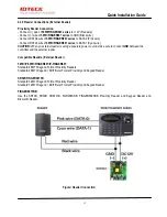
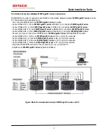
3.2.2 How to Connect Termination Resistors
Figure: Termination Resistors for 4 Wire RS422 Communication System
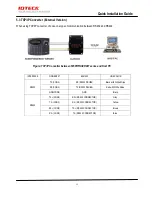
3.2.3 Reverse Diode Connection
If you connect an inductor (Door Locks or Alarm Device) to the output relays, there will be a high surge voltage created
while the inductor is turning on and off. If you do not connect Reverse Diode, the surge voltage will transfer and
damage the electronic circuit of the controller. It is strongly recommended to add a Reverse Diode between the
inductor coils to absorb this surge voltage.
Figure: Reverse Diode Connection


