15
Quick Installation Guide
4-Door Control
Expansion I/O board (EIO88) is required to control 4 doors.
Door 1
External Reader (Reader#1)
Connect to READER#1 port to iTDC/iTDC-SR main board.
Exit Button
Connect to INPUT#1 port of iTDC/iTDC-SR main board.
Door 2
External Reader (Reader#2)
Connect to READER#2 port of iTDC/iTDC-SR main board.
Exit Button
Connect to INPUT#3 port of iTDC/iTDC-SR main board.
Door 3
External Reader (Reader#3)
Connect to READER#3 port of iTDC/iTDC-SR main board.
Exit Button
Connect to INPUT#1 port of EIO88.
Door 4
External Reader (Reader#4)
Connect to READER#4 port of iTDC/iTDC-SR main board.
Exit Button
Connect INPUT#3 port of EIO88.
Make sure to ground GND of external power and GND of iTDC/iTDC-SR as common. Failed to do so may cause
communication error. Noise from outside can cause system troubles and may shorten the product lifetime. RF
reader can use external power.
5. REVERSE DIODE CONNECTION
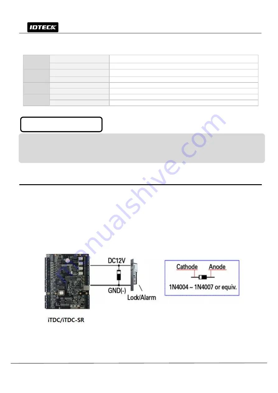
If you connect an inductor (Door Locks or Alarm device) to the output relays, there will be a high surge voltage created
while the inductor is turning on and off. To protect this problem, connect the reverse diode as the figure below.
Caution
It is strongly recommended to add a reverse diode between the inductor coils to absorb this surge voltage.
If you do not connect a reverse diode, the surge voltage will transfer and damage the electronic circuit of the controller.
1N4004 – 1N4007 or equality efficiency diode is included in gift box.
Figure: Reverse Diode Connection
Caution when wiring reader


