13
※
CAUTION
Before mounting the main unit to the Wall Mount bracket, operational test of the unit should be
completed, as the locking pins will lock the unit to the Wall Mount. Removing the unit from the
Wall Mount bracket after they have been installed together may cause damages to the
bracket and render its effectiveness.
8.2.3 Insert 5 O-rings to the wall mount as indicated, then route the cable of the main unit through
the center hole and push the main unit to wall mount to lock the main unit and make sure
that the main unit is locked with wall mount.
8.2 System Initialization
The Hardware initialization must be operated before the RFK505 installation.
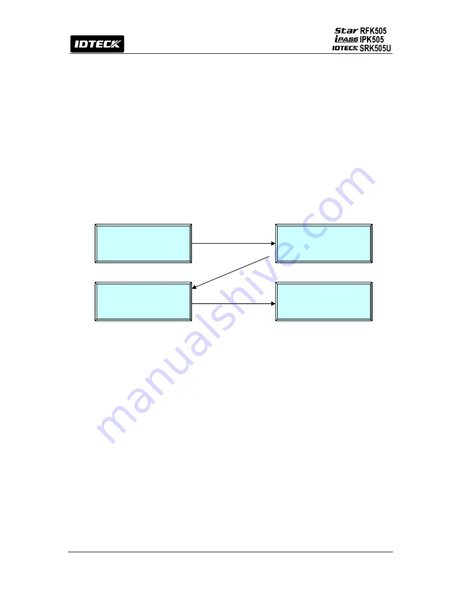
First, turn off the system power and connect 3 wires (pink, cyan and black (GND)), and turn
on the system power. Then, “Initialize beep” will be heard and picture will be displayed.
①
○
1
System Initialize
1 – Yes, 0 - No
○
2
○
4
System is Clear
Remove Wires!!
○
3
System
Initializing...
[ _ _ _ _ ]
Master Password
1. : For Hardware initializing, enter key
①
<1>
.
2.
②
: Enter initial master password(
<3141>
).
3.
③
: Showing initializing.
4.
④
: After initializing – Turn main power
OFF
and separate 3 wires and
turn main power
ON
again.
8
8.3
8.3.2
.3 Wiring
.1 Power
- Connect the (+) wire of DC 12V power to the +12V (Red wire).
- Connect the GND (-) wire of DC 12V power to the GND (Black wire).
Output Connections
Wiegand Data Connection
- Connect Data 0 of the controller to Wiegand Data 0 Out (Green wire).
- Connect Data 1 of the controller to Wiegand Data 1 Out (White wire).
- If you disconnect power from the controller, connect the GND port between controllers.
ABA Track II Connection
- Connect Data 0 of the controller to ABA Track II Data Out (Green wire).
- Connect Data 1 of the controller to ABA Track II Clock Out (White wire).
Содержание iPASS IPK505
Страница 1: ...User s Manual PIN Proximity Card Reader ...
Страница 31: ...31 16 Template ...


