© 2009 IDS Imaging Development Systems GmbH
190
User Manual uEye Cameras V3.32
*
)
For information on how to determine the USB board revision, please refer to the USB
uEye SE Driver Compatibility chapter.
For interpreting the trigger signal, either the positive or the negative edge can be used. The digital
input is galvanically isolated using an opto coupler to protect the camera and the PC against surges.
Only DC voltages may be applied to the digital input.
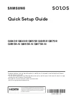
Digital input wiring
Figure 171: Wiring of the trigger connector
Digital Output Wiring (Flash)
Digital output specifications
USB board revision
*
)
1.2
2.0 or higher
Max.
Max.
Output current (short-time)
50
500
mA
Output current (permanent)
15
150
mA
Output voltage
30
30
V
Breakdown voltage
50
50
V
Collector power dissipation
100
125
mW
*
)
For information on how to determine the USB board revision, please refer to the USB
uEye SE Driver Compatibility chapter.
The digital input is galvanically isolated using an opto coupler to protect the camera and the PC
against surges. Only DC voltages may be applied to the digital input.
The output of the opto coupler can be used as an open collector or open emitter output. This means
that the output signal can be connected to ground or to the supply voltage. The output signal is
active if the collector-emitter switch is closed (software setting:
Flash high active
, see also the
Camera Properties: Input/Output section).