

Electronic Pushbutton Locks
EL740S
© 2017 IDN, Inc. All rights reserved.
0817
C
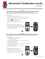
Keypad does not respond
at all.
Programming code cannot
be changed ?
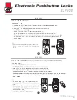
1. Please complete the "HOW TO CHANGE PROGRAMMING CODE"
process by inputting codes within 10 seconds.
2. Please make sure you have entered the new programming code
correctly or go back to the factory setting and reset the programming
code again.
47
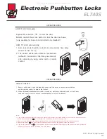
TROUBLESHOOTING GUIDELINE
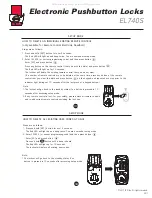
1. Check to see if the batteries are well-installed.
2. Check to see if the Yellow LED light is flashing or not. It means
"low battery" if the light keeps flashing.
3. Make sure the cable is well-connected to the port.
QUESTIONS
ANSWERS
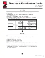
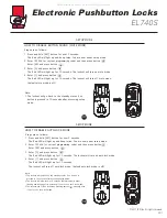
I cannot delete all user codes.
1. Make sure all code inputting processes should be completed within
10 seconds.
2. Make sure you have entered the correct programming code.
3. button should be held over 3 seconds.
I cannot add a new user code.
1. Make sure all code inputting processes should be completed within
10 seconds.
2. Make sure you have entered the correct programming code.
3. The new user code will not be accepted if 10 sets of user codes are
already stored in the memory.
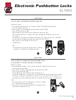
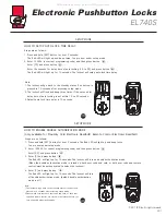
1. Make sure you have entered the correct user code.
2. Check to see if the Yellow LED light is flashing or not. It means
"low battery" if the light keeps flashing.
3. Please make sure the position of strike plate is installed correctly if you
see the latch is jammed.
1. Please refer to "HOW TO RESTORE FACTORY SETTING” section and make
sure all steps are followed correctly.
2. Check to see if the Yellow LED light is flashing or not. It means
"low battery" if the light keeps flashing.
What happens if the lockset
is not able to unlock by the
keypad?
I am unable to reset the
lockset.
48
TROUBLESHOOTING GUIDELINE
QUESTIONS
ANSWERS
All manuals and user guides at all-guides.com


