

Electronic Pushbutton Locks
EL740S
© 2017 IDN, Inc. All rights reserved.
0817
!
!
ATTENTION
INSTRUCTIONS IMPORTANTES DE SECURITE
1. N’utilisez pas de produits abrasifs ou de produits chimiques contenant de l'alcool, du benzene,
de l'acide chlorhydrique ou de l'acide nitrique, et evitez d'utiliser des objets tranchants ou abrasifs
pour nettoyer cette serrure.
2. Ne laissez pas l'eau ou un liquide dans la serrure pendant le processus d'installation.
1. Ne tentez pas de demonter vous-memes les composants internes de la serrure. Vous courez le
risque d'annuler la garantie limitee.
2. Ne laissez pas tomber la serrure. Un grand choc pourrait causer des dommages
permanents.
3. N’utilisez pas des epingles ou des objets tranchants pour appuyer sur le clavier.
4. Creez toujours une copie de sauvegarde des informations que vous souhaitez conserver (telles
que le code de programmation et les codes d'utilisateur). Veuillez utiliser la derniere page de ce
manuel comme reference.
5. Veuillez changer le code de programmation avant d'utiliser cette serrure.
6. Il est fortement recommand
é
que vous utilisez uniquement des piles alcalines pour utiliser ce
produit.
!
!
01B
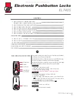
CONTENTS
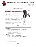
MAIN OPERATING INSTRUCTIONS
PROGRAMMING CODE AND USER CODE
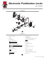
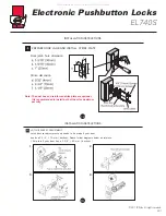
COMPONENTS
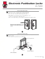
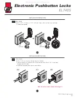
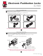
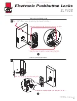
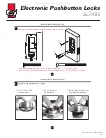
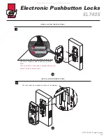
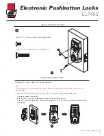
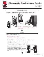
INSTALLATION INSTRUCTIONS
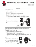
SETUP MODE
01. HOW TO CHANGE PROGRAMMING CODE
02. HOW TO ADD AN USER CODE
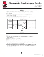
03. HOW TO ADD A PROXIMITY CARD (RFID)
04. HOW TO ADD A REMOTE CONTROL (RADIO FREQUENCY, RF)
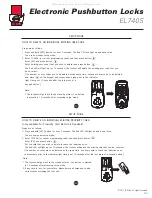
06. HOW TO DELETE AN INDIVIDUAL EXISTING USER CODE
07. HOW TO DELETE AN INDIVIDUAL EXISTING PROXIMITY CARD
08. HOW TO DELETE AN INDIVIDUAL EXISTING REMOTE CONTROL
09. HOW TO DELETE ALL EXISTING USER CODES AT ONCE
10. HOW TO DELETE ALL EXISTING PROXIMITY CARDS/ REMOTE CONTROLS AT ONCE
02A
03
25
35
26
27
28
29
31
33
32
34
05
06
08
05. HOW TO ADD A SINGLE-USE USER CODE/ PROXIMITY CARD/ REMOTE CONTROL
All manuals and user guides at all-guides.com


