26
Falcon GTE -
Installation & Servicing
INSTALLATION
TEST STB
AUT
7
8
9
3
4
6,3 AT
5
6
30
o
c
10
9
8
7
3
4
1
5
6
2
FAL5925
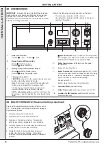
48 COMMISSIONING
IMPORTANT
. Domestic hot water circuits (if they exist and
heating circuits must have been filled and bled, and leak
tightness tests must have been carried out on them, in
accordance with the instructions for the domestic hot water
calorifier (if existing) and boiler.
1.
Boiler on/off switch.
Position .....ON
Position .....OFF
2.
Burner Summer/Winter switch:
Winter
starts the burner.
Summer
stops the burner.
3.
Heating Pump Summer/Winter Switch:
Winter
starts the heating pump.
Summer
stops the heating pump.
4.
Three-position switch:
TEST STB:
when held in the pressed (momentary use)
position it tests the safety thermostat.
Note
. If two stage burner control fitted operation will
continue on 1st stage after 2nd stage cut-off.
The heating pump switch (3) may be put in the
Summer position while performing this test.
AUTO : automatic position,
used for normal operation
of the boiler. Use this position if a room thermostat is
fitted.
: Manual Position:
may be used for normal operation
if two stage burner fitted, but overrides room thermostat
(if fitted) when ON/OFF burner operation fitted.
5.
Boiler thermometer:
indicates boiler flow water
temperature.
6.
Fuse:
6.3 amp timed fuse.
7.
Boiler Thermostat:
Adjustment range 30-90
o
C for ON/
OFF burners and 30-90
o
C 1st Stage, 26-86
o
C 2nd stage
for two stage burners. (Automatic changeover from
high to low fire at 4
o
below the flow setting.)
Factory set at 75
o
C.
Built in stops may be reset (See Frame 49).
8.
Hour Run Meter:
(optional if fitted).
9.
Safety Thermostat:
(with manual reset) set at 110
o
C.
10.
Location for MB1 module:
used for DHW control on
Combi models only.
Refer to the following instructions to start up the boiler.
-
the instructions delivered with the burner.
-
the instructions delivered with the domestic hot water
calorifier, (if existing).
49 BOILER THERMOSTAT (Maximum Setting Adjustment)
The boiler thermostat maximum setting is factory set at
75
o
C. The fixed stop controlling the maximum setting is
adjustable as follows:
1. Carefully remove the control knob.
2. Pull out the pin from the back of the knob.
3. Relocate in the desired position. Temperature
settings are marked alongside the pin locations.
4. Carefully replace the knob ensuring that the new pin
position is at the correct side of the stop.
5. Rotate the knob to the new desired maximum
position to check correct setting. (The setting
numbers 3-9 are approximately scaled to represent
30-90
o
C).
80+
5
0+
75+
30-
35-
40-
45
-
50-
90+
70+
80+
5
0+
75+
30-
35-
40-
45
-
50-
90+
70+
fal5934
INST
ALLA
TION
Содержание Falcon GTE 4
Страница 30: ...30 Falcon GTE Installation Servicing NOTES...
Страница 31: ...31 Falcon GTE Installation Servicing NOTES...

