background image

EVOMAX - MULTILINE FLUE KITS

9

COMMISSIONING

4.1 EVOMAX CASCADE FLUE SYSTEM – MINIMUM RATE BOILER SETTINGS & DATA 

Evomax Boiler Model

30

30P

40

40P

60

60P

80

80P

100

120

150

Fan Speed

rpm

1980

2100

2400

2340

1800

1800

2340

2220

2280

1860

1800

Input

net

kW

7.6

7.6

10.1

10.1

15.2

15.2

20.5

20.5

25.6

30.7

38.4

gross

kW

8.4

8.3

11.2

11.0

16.9

16.5

22.7

22.3

28.4

34.1

42.6

Output 

non-condensing

kW

7.5

7.5

10

10

15.0

15.0

20

20

25.0

30.0

37.5

Output 

condensing

kW

8.0

7.8

10.7

10.4

16.0

15.7

21.6

21.2

27.0

32.4

40.5

Flue CO

2

± 0.5

%

9.0

10.6

9.0

10.6

9.0

10.6

9.0

10.6

9.0

9.0

9.0

NOx 

(weighted)

Cat 5

mg/kWh

33

82

41

84

35

84

42

68

43.5

41

40.5

4.0 COMMISSIONING

To accommodate the flue pressure generated by the 

connection of multiple boilers to a common flue, the minimum 

rate (equivalent to minimum fan speed) of each Evomax 

appliance operating on the Multiline cascade system is 

increased to offset the maximum back-pressure created. 

Table 4.1 shows the revised performance of each Evomax 

model where it differs from standard standalone operation as 

shown in the Evomax Installation & Servicing instructions.

To convert Evomax operation with the Multiline flue as 

described, the change is made by accessing the operating 

parameters on the Evomax user interface control panel 

following the procedure below. This change must be made to 

each Evomax operating on the Multiline cascade system.

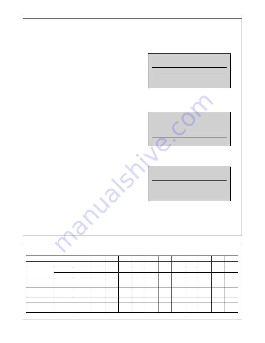
Procedure for selecting Multiline cascade flue operation 

on Evomax user interface control panel.

1.0 

Press SELECT and then hold + and – buttons down 


together for more then 5 seconds, the following screen 


will be displayed.

2.0 

Rotate the KNOB clockwise and scroll downwards 


towards the end of the list until the following screen is 


displayed.

3.0 

Press SELECT and the following screen will be 


displayed.

4.0 

Press + or - to highlight ‘Multiline Flue’ and then press 


ENTER to store.

5.0 

Rotate the KNOB clockwise until Normal Operation  


is highlighted again and press SELECT to return to  


normal operation.

INSTALLER MODE

NORMAL OPERATION 

SET FLOW TEMP’


SET DHW TEMP’

INSTALLER MODE

FLAME/LPG RELAY


FLUE SETTING 

NORMAL OPERATION

INSTALLER MODE

STANDARD FLUE 

MULTILINE FLUE

Содержание Evomax 30

Страница 1: ...ured conform to the safety and performance specification that we require Do not use reconditioned or copy parts that have not been clearly authorised by Ideal For the very latest copy of literature fo...

Страница 2: ...2 GENERAL CONTENTS Introduction 3 Cascade Flue Components 4 Assembly 5 Flue Design 6 Commissioning 9 Starter Kit Components 10 Extension Kit Components 12 NOTE TO THE INSTALLER LEAVE THESE INSTRUCTION...

Страница 3: ...eptable operation of any individual boiler operating at its minimum output under the influence of the total system pressure generated by the adjacent boilers There are optional system configurations t...

Страница 4: ...g clips are also provided to prevent movement of the tube connections by the influence of expansion and contraction These must be fitted to the ductwork to ensure safe operation of the system 2 2 STAR...

Страница 5: ...the 30 80 models or 100 150 models the inner tube is manufactured in Polypropylene in accordance with the cascade system Flue connectors with an aluminium inner tube must not be used 2 7 WIRE RETAINI...

Страница 6: ...ORTANT LEAKAGE OF FLUE PRODUCTS INTO THE ROOM WILL DEPLETE THE OXYGEN LEVEL INHIBIT SAFE COMBUSTION 3 0 7 The flue route should be planned to enable the least directional change one elbow is recommend...

Страница 7: ...d components A A At the maximum system capacity the static pressure generated against the flue resistance at position A must not exceed the value Pmax quoted in Table 3 3 3 3 EVOMAX CASCADE FLUE SYSTE...

Страница 8: ...600 650 0 100 200 300 400 500 600 700 800 900 1000 1100 Mass Flow Rate kg hr Volume Flow Rate mean flue temp 50C cu m hr Cascade Total System Capacity Htot kW Cascade Flow Rate Qmax Cascade Total Sys...

Страница 9: ...of each Evomax model where it differs from standard standalone operation as shown in the Evomax Installation Servicing instructions To convert Evomax operation with the Multiline flue as described th...

Страница 10: ...1 AIR INLET GRILL AL 125 80 H 85 3 1 EXTENSION PP 80x500 4 1 VALVE PP 80 150 5 1 REDUCER EXC PP 150 100 6 1 ELBOW SHORT PP 100 90 7 1 COLLECTOR PP 200x610 1x100 45 8 1 COVER PP 200 CONDENSATE 9 1 SYP...

Страница 11: ...0 150 MP 2 1 AIR INLET GRILL AL 150 100 H 85 3 1 EXTENSION PP 100x500 4 1 VALVE PP 100 150 5 1 REDUCER EXC PP 150 100 6 1 ELBOW SHORT PP 100 90 7 1 COLLECTOR PP 200x610 1x100 45 8 1 COVER PP 200 CONDE...

Страница 12: ...ADAPTER CONCENTRIC PP 80 125 MP 2 1 AIR INLET GRILL AL 125 80 H 85 3 1 EXTENSION PP 80x500 4 1 VALVE PP 80 150 5 1 REDUCER EXC PP 150 100 6 1 ELBOW SHORT PP 100 90 7 1 COLLECTOR PP 200x610 1x100 45 8...

Страница 13: ...ION 1 1 ADAPTER CONCENTRIC PP 100 150 MP 2 1 AIR INLET GRILL AL 150 100 H 85 3 1 EXTENSION PP 100x500 4 1 VALVE PP 100 150 5 1 REDUCER EXC PP 150 100 6 1 ELBOW SHORT PP 100 90 7 1 COLLECTOR PP 200x610...

Страница 14: ...NOTES 14 EVOMAX MULTILINE FLUE KITS...

Страница 15: ...NOTES 15 EVOMAX MULTILINE FLUE KITS...

Страница 16: ...tinuing improvement in the design and performance of its products The right is therefore reserved to vary specification without notice The Ideal Boilers Technical Training Centre offers a series of fi...

Отзывы: