INSTALLATION
Mini
--- Installation & Servicing
24
26 EXTERNAL ELECTRICAL CONTROLS
Wiring external to the boiler MUST be in accordance with the
current I.E.E. (BS.7671) Wiring Regulations.
For Ireland reference should be made to the current ETCI
rules for electrical installations.
The fuse rating should be 3.15 AF.
Route the electrical supply flexible cord and the external
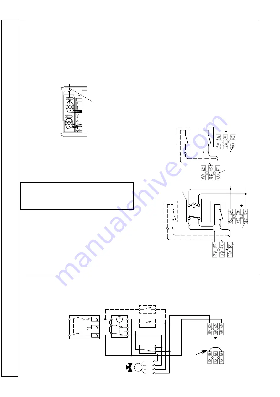
control flexible cord as illustrated.
Lock the flexible cords in place with the clamps provided.
230V supply
ELECTRICAL CONNECTIONS FOR A
COMBI BOILER
Optional Programmer Kit
For the models
Mini C24
,
Mini C28
and
Mini C32
(combi) an
optional digital programmer kit is available with its relevant
instructions.
Note: the switch contacts of any external programmer,
room or frost thermostat must be volt free.
Connecting a switched live feed to external controls
terminal block may be dangerous and will result in
serious damage to the boiler.
Room Thermostat
This should be wired as shown in diagrams A.
Frost protection
Central heating systems fitted wholly inside the house do not
normally require frost protection as the house acts as a
‘storage heater’ and can normally be left at least 24 hours
without frost damage.
However, if parts of the pipework run outside the house or if
the boiler will be left off for more than a day or so then a frost
thermostat should be wired into the system. To maintain frost
protection with the programmer selector switches set to OFF,
all the controls MUST be left in the running position.
The frost thermostat should be sited in a cold place but where
it can sense heat from the system.
Wiring should be as shown, with minimal disturbance to other
wiring.
External Programmers
On the combi boilers, this should be of the single channel
type (as this boiler does not incorporate a pre---heat facility for
the instantaneous hot water service).
For system boliers refer to frame 27.
Programmers with room thermostat --- see diagram B.
Note. lf the boiler is installed in a garage it may be necessary
to fit a pipe thermostat, preferably on the return pipework.
Earths are not shown for clarity but must never be omitted.
A
Power supply
terminal block
External controls
terminal block
T
Room thermostat
T
Optional frost’stat
1
2
L
N
3
B
Power supply
terminal block
External controls
terminal block
T
Room thermostat
T
Optional frost’stat
1
2
L
N
3
External programmer
N.B. These diagrams are schematic only and do not show
external terminal strips etc.
27 ELECTRICAL CONNECTIONS FOR A
SYSTEM BOILER
The following diagram shows a possible way to connect an
external programmer to a mid---position diverter valve to
provide independent timed and thermostatic control of
heating and water.
The earth wires are not shown for clarity. Earth wiring must be
fitted as necessary
BL
GR
BR
OR
Valve colour key
BR --- Brown
BL --- Blue
GR --- Grey
OR --- Orange
MAINS
230V a.c.
Switched 3 Amp fused,
spur
Programmer
Room thermostat
Cylinder
thermostat
Mid--- position
diverter valve
L
N
Do not
remove
Power supply
terminal block
L
N
3
2
1
Optional frost’stat
INST
ALLA
TION
Содержание 41-392-98
Страница 2: ...2 Mini Installation Servicing ...


