
Innovative Circuit Technology Ltd.
9
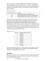
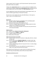
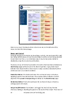
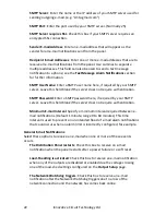
Figure 2: Fuse Version Front Panel
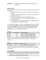
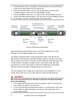
Energise each bus by closing the main external breaker or disconnect device on
the bus input lines. Check that the Distribution Panel LCD display powers up, the
internal channel relays close after a short delay, and the connected loads are
energised. (Note that all output channels on a bus will be disabled if the bus
voltage drops below 6V for more than 3s. Normal operation will be restored once
the bus voltage is above 8V)
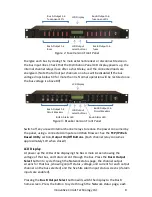
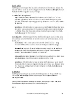
Figure 3: Breaker Version Front Panel
Switch off any unused internal channel relays to reduce the power consumed by
the panel, using a connected computer and Web Browser. See the
TCP/IP Web
Based Utility
section,
Output On/Off Buttons
. (Each channel relay consumes
approximately 1W when closed)
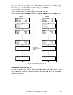
LCD Display
At power up the LCD will be displaying the Bus A main screen showing the
voltage of that bus, and total current through the bus. Press the
Bus A
Output
Select
button to cycle through the Network status page, the channel output
screens for that bus, (showing on/off status, voltage, and current for each output
channel on the bus selected) and the five Site Alarm input status screens (if alarm
inputs are enabled).
Pressing the
Bus B Output Select
button will switch the display to the Bus B
home screen. Press the button to cycle through the Network status page, each
LCD Output
select buttons
Bus A Output 1-6
fuses
Bus B Output 1-6
fuses
Bus A Output 1-6
fuse open LED’s
Bus B Output 1-6
fuse open LED’s
LCD Output
select buttons
Bus B Output 1-6
Circuit Breakers
Bus A Output 1-6
Circuit Breakers
BUS A Alarm LED
Bus B Alarm LED
LCD Display
LCD Display


