
Innovative Circuit Technology Ltd.
11
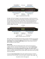
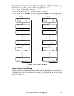
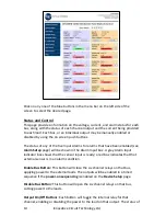
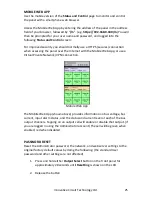
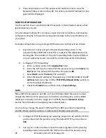
The alarm screens are displayed only if the alarm input has been enabled using
the Alarm Setup section of the web based graphic interface
Line 1: Alarm input number (1 to 5)
Line 2: Name of the alarm (if configured, default is blank)
Line 4: Alarm Status (
ALARM
if alarm is triggered,
READY
when not triggered)
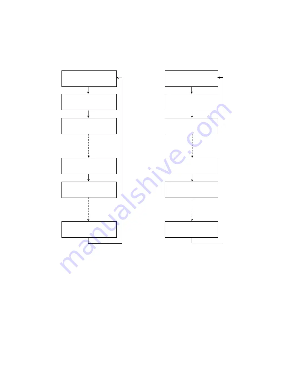
Figure 4: LCD Display Screens
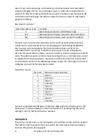
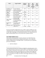
Status Indicators and Alarms
The channel LEDs (fuse version) and the Bus Alarm LEDs (breaker version) on the
front panel and the Form-C Bus Alarm contacts on the back are used to indicate
an alarm condition.
BUS A MENU
BUS B MENU
BUS:
"A"
BUS:
"B"
SYS VOLTAGE:
13.80V
SYS VOLTAGE:
-51.2V
BUS CURRENT:
76.4A
BUS CURRENT:
32.5A
100 Base-T
100 Base-T
182.168.0.180
182.168.0.180
00:50:C2:02:10:2C
00:50:C2:02:10:2C
STATUS:
ENABLED
STATUS:
ENABLED
VOLTAGE:
13.80V
VOLTAGE:
-51.2V
CURRENT:
14.5A
CURRENT:
8.7A
STATUS:
ENABLED
STATUS:
ENABLED
VOLTAGE:
13.80V
VOLTAGE:
-51.2V
CURRENT:
0.0A
CURRENT:
0.0A
STATUS
READY
STATUS
READY
STATUS
ALARM
STATUS
ALARM
ICT DUAL BUS PANEL
Network Connected
OUTPUT 1B
OUTPUT 6B
ALARM INPUT #1
ALARM INPUT #5
ICT DUAL BUS PANEL
Network Connected
OUTPUT 1A
OUTPUT 6A
ALARM INPUT #1
ALARM INPUT #5
Alarm screens
displayed only if alarm
enabled


