71
z
Display
z
Channel
name
Please highlight icon
to select the corresponding function.
After all the setups please click OK button, system goes back to the previous menu.
Warning!
System menu color, language, time display mode, video format, IP address, user account will not
maintain previous setup after default operation!
4.6.11
Remote Device
Important
Do not connect the switch to the PoE port, otherwise the connection may fail!
4.6.11.1 UPNP
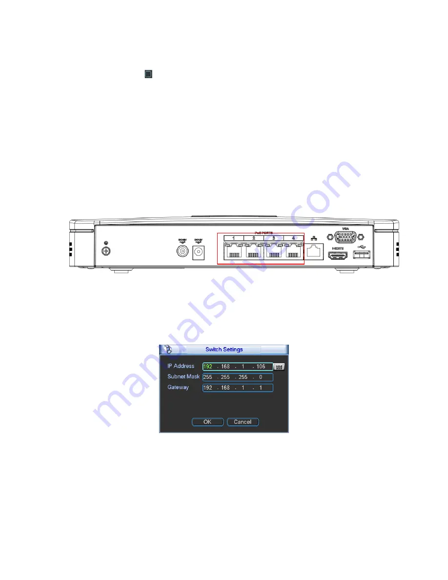
Please connect the IPC to the PoE port of the device rear panel (Figure 4-74), system can auto
connect to the network camera. Please note the following figure is for reference only.
Figure 4-74
4.6.11.2 Built-in Switch Setup
The built-in switch function is for product of PoE port.
From Network->Network Server->Switch, you can set switch IP address, subnet mask, gateway
and etc. See Figure 4-75.
Figure 4-75
4.6.11.3 Remote Device
In the main menu, click the Remote Device icon to go to the corresponding interface. See Figure
4-76.
Содержание NVR4i Series
Страница 1: ...ICRealtime Network Video Recorder User s Manual V 3 1 0 ...
Страница 16: ...7 Weight 5 5 6 5 KG Exclude HDD Installation Desk installation ...
Страница 49: ...40 Figure 4 21 Figure 4 22 Figure 4 23 Figure 4 24 ...
Страница 51: ...42 Please highlight icon to select the corresponding function Figure 4 26 Figure 4 27 Figure 4 28 ...
Страница 71: ...62 Figure 4 55 Figure 4 56 Figure 4 57 ...
Страница 95: ...86 Figure 4 100 ...
Страница 129: ...120 signal which meets the senility standard that is previously set See Figure 6 42 ...
Страница 162: ...153 Teclast Ti Cool 512M Teclast Ti Cool 1G Teclast Ti Cool 2G ...


