44
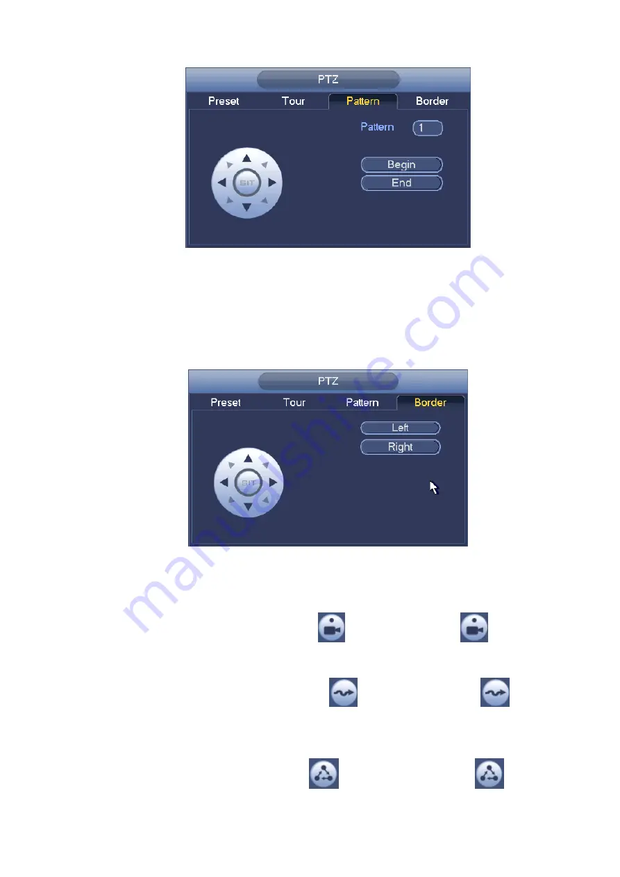
Figure 4-45
Scan Setup
In
Figure 4-42, click Scan button.
Use direction buttons to set camera left limit and then click Left button.
Use direction buttons to set camera right limit and then click Right button. Now the scan setup process is
complete.
Figure 4-46
4.7.2.2 Call PTZ Function
Call Preset
In Figure 4-41, input preset value and then click
to call a preset. Click
again to stop call.
Call Pattern
In Figure 4-41, input pattern value and then click
to call a pattern. Click
again to stop
call.
Call Tour
In Figure 4-41, input tour value and then click
to call a tour. Click again
to stop call.
Содержание NVR-7508K
Страница 1: ...Network Video Recorder User s Manual V 2 0 0 ...
Страница 8: ...vii 9 Appendix B Compatible Network Camera List 217 ...
Страница 85: ...74 Figure 4 81 Figure 4 82 ...
Страница 86: ...75 Figure 4 83 Figure 4 84 ...
Страница 92: ...81 Figure 4 89 Figure 4 90 ...
Страница 93: ...82 Figure 4 91 Figure 4 92 ...
Страница 94: ...83 Figure 4 93 Figure 4 94 ...
Страница 96: ...85 Figure 4 96 Figure 4 97 ...
Страница 122: ...111 Figure 4 125 In Figure 4 125 click one HDD item the S M A R T interface is shown as in Figure 4 126 Figure 4 126 ...
Страница 183: ...172 The motion detect interface is shown as in Figure 5 54 Figure 5 54 Figure 5 55 ...
Страница 184: ...173 Figure 5 56 Figure 5 57 Figure 5 58 ...
Страница 188: ...177 Figure 5 62 Figure 5 63 ...


