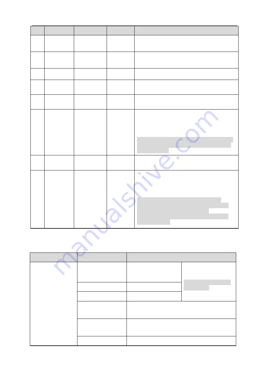
ICRealtime IPFX-S20F-W1 Скачать руководство пользователя страница 8


14 

No. 

Port  

Port name 

connector  Function description  

AUDIO 
OUT 

Audio output 

port 

3.5mm 
TRS 

Output audio signal to the speakers and other 

devices. 

AUDIO IN 

Audio input 

port 

3.5mm 
TRS 

Input audio signal, receive analog audio signal 

from pickup and other devices. 

SD 
Card 

Micro SD  

Micro SD 
Card slot 

Micro SD card storage. 

SENSOR 

Sensor port 

Sensor 
board  

Connect  front  end  sensor  board,  acquire 
image data. 

LAN 

Network port  

Ethernet 
port  

Connect  to  standard  Ethernet  cable,  provide 
PoE power supply function.  

DC12V 

Power input 

port  

Input DC12V; please be sure to power the 
device according to the instruction of device 
label. 

Caution 

It may cause damage to the device if it fails to 
power the device according to the instruction 
of device label. 

I/O 

I/O port  

Alarm  input  and  output;  refer  to  Table  1-2  for 
more details.  

Reset 
Button  

Reset 

It is used to restore factory default settings for 
the device. 

Note 

Continuously press the button for over 5 
seconds in the situation where the device is 
working normally, then the system 
configuration info can be restored to factory 
default settings.  

Table 1-1  


Port name  

Cable port name  

Function description 

I/O port  

Ground terminal 
connecting to RS232 
serial port. 

Note  

Some devices support 
RS485 port.  

TX 

RS232 sending port. 

RX 

RS232 receiving port. 

IN1 

Alarm input port 1

receive on-off signal from 

external alarm source. 

IN2 

Alarm input port 2

receive on-off signal from 

external alarm source (reserved).  

Alarm GND 

Содержание IPFX-S20F-W1

Страница 1: ...HD Pinhole Network Camera Quick Start Guide Version 1 0 0 ...

Страница 2: ...proper handling or installation Environment Do not aim the device at strong light to focus such as lamp light and sun light otherwise it might cause over brightness or light marks which are not the device malfunction and affect the longevity of Charge Coupled Device CCD or Complementary Metal Oxide Semiconductor CMOS Do not place the device in a damp or dusty environment extremely hot or cold temp...

Страница 3: ... or air blower to gently wipe it away If stained with grease or fingerprint use soft cloth to gently wipe the water drop or oil and wait till it is dry and then use oil free cotton cloth or lens cleaning paper soaked with alcohol or detergent to wipe from the lens center outward till it is clean We are not liable for any problems caused by unauthorized modification or attempted repair The dome cov...

Страница 4: ...ulatory Information FCC Information 1 1 FCC conditions This device complies with part 15 of the FCC Rules Operation is subject to the following two conditions This device may not cause harmful interference This device must accept any interference received including interference that may cause undesired operation 1 2 FCC compliance This equipment has been tested and found to comply with the limits ...

Страница 5: ...stallation please open the package and check all the components are included Contact your local retailer as soon as possible if something is broken in your package Accessory Name Amount Accessory Name Amount Network Camera 1 Installation Position Map 1 Quick Start Guide 1 Screw Package 1 CD 1 Decoration Cover Optional 1 ...

Страница 6: ...le of Contents 1 Device Framework 17 1 1 External Cable 17 1 2 Dimension 19 2 Device Installation 20 3 Network Configuration 24 3 1 Device Initialization 24 3 2 Modify IP Address 26 3 3 Login WEB Interface 26 ...

Страница 7: ...ts and cable ports There might be some minor differences between different devices so please refer to the actual products you purchased Please refer to Figure 1 1 and Figure 1 2 for the structure of front panel Figure 1 1 Figure 1 2 Please refer to Figure 1 3 for the structure of rear panel Figure 1 3 The following tables show more information about port function ...

Страница 8: ...Caution It may cause damage to the device if it fails to power the device according to the instruction of device label 7 I O I O port Alarm input and output refer to Table 1 2 for more details 8 Reset Button Reset It is used to restore factory default settings for the device Note Continuously press the button for over 5 seconds in the situation where the device is working normally then the system ...

Страница 9: ...vice C1 N2 Alarm output port 2 reserved C2 Table 1 2 1 2 Dimension Refer to Figure 1 4 for the dimension of Model A The unit is mm inch Figure 1 4 Refer to Figure 1 5 for the dimension of Model B The unit is mm inch Figure 1 5 Refer to Figure 1 6 for the dimension of Model C The unit is mm inch Figure 1 6 ...

Страница 10: ... the device need to be installed respectively There are four types of shape for front part Note The following figures are for reference only please refer to the product for more details Make sure the bracket installation surface can sustain at least 3X weight of the total weight of bracket and camera The device is not equipped with bracket by default please purchase it separately if necessary Step...

Страница 11: ...d insert them into the holes you just dug 3 Take out self tapping screws and tighten 3 screws to fix the device on the installation surface where the bolts are located 4 Put the device into the mounting bracket directly 5 Connect front end lens to camera body via cable Step 2 Front part installation for model A B C and D optional Please select installation mode according to the actual situation No...

Страница 12: ...eeds to implement the following steps when it is model D Figure 2 3 1 Take out mounting bracket from the accessories bag including adjusting screw rotation fixing ring pedestal and inner barrel 2 Put the round lens into the inner barrel properly 3 Twist the rotation fixing ring into the inner barrel and make sure the round lens is firmly fixed 4 Rotate the lens to a proper angle lock the adjusting...

Страница 13: ...quirement and then use insulated tape to twine the connection respectively to make it waterproof Connect alarm input and output terminal to external cable according to Connect Alarm Input output Port and use insulated tape to twine connection to make it waterproof Connect Alarm Input Output Port Note Some models do not support alarm function which cannot be applied to this chapter Step 1 Connect a...

Страница 14: ... port of the I O port cable 3 Network Configuration You can initialize the device and modify IP address via Quick Configuration Tool you can also initialize device and modify IP address on the WEB interface Please refer to the WEB Operation Manual in the disk for more details Note It needs to implement initialization if it is the first time use device or the device is restored to factory default O...

Страница 15: ...Device Initialization which is shown in Figure 3 1 Figure 3 1 Step 5 Set new password and confirm password select Email Address and input email address Note The password can be set as 8 to 32 characters it can be a combination of number s letter s and symbol s with at least two kinds of them excluding Please set password with high security according to the password strong and weak prompt Step 6 Cl...

Страница 16: ... click The system will display the dialog box of Modify IP Address which is shown in Figure 3 2 Figure 3 2 Step 5 Set the mode as Static and enter the planned start IP subnet mask and gateway Note Set the mode as DHCP when there is DHCP server in the network the device will automatically acquire IP address from the DHCP server Step 6 Click OK to complete modification of device IP address 3 3 Login...

Страница 17: ...d password click Login Step 3 For the first login click Click Here to Download Plug in install controls according to system prompt The main interface will be shown in Figure 3 3 after control installation is completed Figure 3 3 ...

Отзывы: