15
2
Framework
2.1
Rear Panel
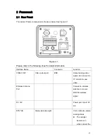
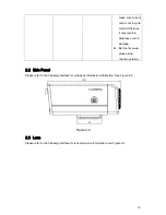
This series IP camera real panel is shown as below. See Figure 2-1.
Figure 2-1
Please refer to the following sheet for detail information.
Interface Name
Connector
Function
VIDEO OUT
Video output port
BNC
Output analog video
signal. Can connect to
TV monitor to view
video.
Wireless Antenna
Port
Connect to wireless
antenna to receive
WIFI/3G wireless
signal.
DC 12V
Power port. Input 12V
DC
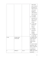
STATUS
Status indication light
It is to indicate camera
working status:
z
The red light
becomes on
when connect the
Содержание F Series
Страница 1: ...F Series Indoor IP Camera User s Manual For F725 F726 F715 F665 F645 F625 series only ...
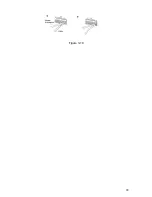
Страница 28: ...28 Figure 3 10 ...
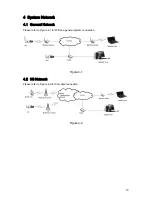
Страница 32: ...32 Figure 5 5 ...


