background image

516 01 3604 04

Specifications subject to change without notice.

39

TWO-SPEED FAN OPERATION
The W7220 controller has the capability to work with a sys

-

tem using a 2-speed supply fan. The W7220 does not con

-

trol the supply directly but uses the following input status to

determine the speed of the supply fan and controls the OA

damper to the required position.

The W (heating mode) is not controlled by the W7220 but it

requires the status to know where to position the OA damp

-

er for minimum position for the fan speed.

The 2-speed fan delay is available when the system is pro

-

grammed for 2-speed fan (in the System Setup menu item).

The 2-speed fan delay is defaulted to 5 minutes and can be

changed in the Advanced Setup menu item. When the unit

has a call for Y1 In and in the free cooling mode and there is

a call for Y2 In, the 2-speed fan delay starts and the OA

damper will modulate 100% open, the supply fan should be

set to high speed by the unit controller.

After the delay one of two actions will happen:

• The Y2 In call will be satisfied with the damper 100%

open and fan on high speed and the call will turn off

OR

• If the call for additional cooling in the space has not

been satisfied then the first stage of mechanical cool

-

ing will be enabled through Y1 Out or Y2 Out.

CHECKOUT
Inspect all wiring connections at the economizer module’s

terminals, and verify compliance with the installation wiring

diagrams. For checkout, review the Status of each config

-

ured parameter and perform the Checkout tests.

For information about menu navigation and use of the key

-

pad see Interface Overview on page 29.

Power Up

After  the  W7220  module  is  mounted  and  wired,  apply

power.

Initial Menu Display

On initial start up, Honeywell displays on the first line and

economizer W7220 on the second line. After a brief pause,

the revision of the software appears on the first line and the

second line is blank.

Power Loss (Outage or Brownout)

All setpoints and advanced settings are restored after any

power loss or interruption.

NOTE: All settings are stored in non-volatile flash memory.

Status

Use the Status menu (see Table 12) to check the parameter

values for the various devices and sensors configured.

NOTE: For information about menu navigation and use of

the keypad see Interface Overview on page 29.

Checkout Tests

Use the Checkout menu (see page 34) to test the damper

operation and any configured outputs. Only items that are

configured are shown in the Checkout menu.

NOTE: For information about menu navigation and use of

the keypad see Interface Overview on page 29.

To perform a Checkout test:

1. Scroll to the desired test in the Checkout menu using

the ▲ and ▼ buttons. 

2. Press the 

 (Enter) button to select the item. RUN?

appears. 

3. Press the 

 (Enter) button to start the test. The unit

pauses and then displays IN PROGRESS. When the

test is complete, DONE appears. 

4. When  all  desired  parameters  have  been  tested,

press the   (Menu Up/Exit) button to end the test.

The Checkout tests can all be performed at the time of in

-

stallation or at any time during the operation of the system

as a test that the system is operable.

TROUBLESHOOTING

Alarms

The economizer module provides alarm messages that dis

-

play on the 2-line LCD.

NOTE: Upon power up, the module waits 60 minutes before

checking for alarms. This allows time for all the configured

devices (e.g. sensors, actuator) to become operational. The

exception is the SAT sensor which will alarm immediately.

If one or more alarms are present and there has been no

keypad activity for at least 5 minutes, the Alarms menu dis

-

plays and cycles through the active alarms.

You can also navigate to the Alarms menu at any time.

Clearing Alarms

Once the alarm has been identified and the cause has been

removed  (e.g.  replaced  faulty  sensor)  the  alarm  can  be

cleared from the display.

To clear an alarm, perform the following:

1. Navigate to the desired alarm.

2. Press the 

 (Enter) button. ERASE? displays.

3. Press  the 

  (Enter)  button.  ALARM  ERASED

displays.

4. Press the   (Menu Up/Exit) button to complete the

action and return to the previous menu.

NOTE:  If  the  alarm  still  exists  after  clearing  it,  it  is  redis

-

played within 5 seconds.

STATE

FAN SPEED

OCC

Low

Y1

Low

Y2

High

W

High

WARNING

ELECTRIC SHOCK HAZARD

Failure to follow this warning could result in personal in

-

jury, property damage, or death. 

Before performing service or maintenance operations on

unit, always turn off main power switch to unit and install

lock(s) and lockout tag(s). Unit may have more than one

power  switch.  Ensure  electrical  service  to  rooftop  unit

agrees with voltage and amperage listed on the unit rat

-

ing plate.

If any wiring changes are required, first be sure to re

-

move power from the economizer module before starting

work. Pay particular attention to verifying the power con

-

nection (24 vac).

CAUTION

EQUIPMENT DAMAGE HAZARD

Failure  to  follow  this  caution  may  result  in  equipment

damage.

Be  sure to  allow  enough time for  compressor  start-up

and shutdown  between  checkout tests so that  you do

not short-cycle the compressors.

Содержание RHH120

Страница 1: ...RING DIAGRAMS Economi er X Factory Option 27 SYSTEM COMPONENTS SPECIFICATIONS INPUTS OUTPUTS ENVIRONMENTAL ECONOMIZER MODULE WIRING DETAILS INTERFACE OVERVIEW ENTHALPY SETTINGS TWO SPEED FAN OPERATION...

Страница 2: ...t DANGER ELECTRICAL SHOCK HAZARD Failure to follow this warning will result in personal injury or death Before performing service or maintenance operations on unit turn off main power switch to unit a...

Страница 3: ...Enthalpy Sensor P 2 Position Damper w Barometric Relief U Ultra Low Leak Economizer w Barometric Relief OA Temp Sensor W Ultra Low Leak Economizer w Barometric Relief Enthalpy Sensor Outdoor Air Optio...

Страница 4: ...4 Specifications subject to change without notice 516 01 3604 04 Fig 2 Unit Dimensional Drawing Size 120 Units...

Страница 5: ...516 01 3604 04 Specifications subject to change without notice 5 Fig 2 Unit Dimensional Drawing Size 120 Units cont...

Страница 6: ...clearances LOCATION DIMENSION CONDITION A 48 in 1219 mm 18 in 457 mm 18 in 457 mm 12 in 305 mm Unit disconnect is mounted on panel No disconnect convenience outlet option Recommended service clearance...

Страница 7: ...o the check valve core s bottom O ring Install the fitting body and torque to 96 10 in lbs 10 9 1 Nm Do not exceed 106 in lbs 11 9 Nm when tightening INSTALLATION Jobsite Survey Complete the following...

Страница 8: ...ing 8 Make electrical connections 9 Install other accessories FRAME MOUNTED INSTALLATION Frame mounted applications generally follow the sequence for a curb installation Adapt the sequence as required...

Страница 9: ...516 01 3604 04 Specifications subject to change without notice 9 Fig 6 Roof Curb Details REV 50TM500827...

Страница 10: ...t is ready to be rigged and no longer will be lift ed by a fork truck the wood protector under the basepan must be removed Remove 4 screws from each base rail Wood protector will drop to the ground Se...

Страница 11: ...iscard the supply duct cover Install accessory CRDUCTCV001A00 to cover the vertical supply duct open ing Use the return duct cover removed from the unit end panel to cover the vertical return duct ope...

Страница 12: ...own form and assembled to a metal support tray using plastic stretch wrap Located in the return air compartment the assembly s metal tray is at tached to the basepan and also attached to the damper us...

Страница 13: ...e hood sides See Fig 17 and 18 Secure hood divider with 3 screws on each hood side The hood divider is also used as the bottom filter rack for the aluminum filter 5 Attach the post that separates the...

Страница 14: ...must be used to route the main power from the condenser end of the unit to either the factory option disconnect the bottom of the control box or the single point box accessory One inch conduit is pro...

Страница 15: ...1 4 in female spade connector from the 230 v connection and moving it to the 200 v 1 4 in male terminal on the prima ry side of the transformer Refer to unit label diagram for ad ditional information...

Страница 16: ...m deviation is 4 v Determine percent of voltage imbalance This amount of phase imbalance is satisfactory as it is below the maxi mum allowable 2 Operation on improper line voltage or excessive phase i...

Страница 17: ...socket re install 3 hex screws on the NFD enclosure 12 Re install the unit front panel Fig 29 Handle and Shaft Assembly for NFD CONVENIENCE OUTLETS Two types of convenience outlets are offered on RHH...

Страница 18: ...the bottom of the dis connect box For the load side wiring to the factory option disconnect route the wires through the hole on the right side of the disconnect Be sure to create a drip loop at least...

Страница 19: ...conduits Connect the power con duit to the internal disconnect if unit is so equipped or to the external disconnect through unit side panel Remove one of the two knockouts located on the bottom left...

Страница 20: ...ng valve position Reversing valves are ener gized during the cooling stages and the defrost cycle and de energized during heating cycles Once energized at the start of a cooling stage the reversing va...

Страница 21: ...DI 24 vac P2 4 CTB Y2 W1 Heat 1 DI 24 vac P2 7 CTB W1 W2 Heat 2 DI 24 vac P2 6 CTB W2 R Power 24 vac P3 1 CONTL BRD 8 C Common 24 vac P3 2 CONTL BRD 4 DFT 1 DI 24 vac DFT 1 to DFT 1 DFT 2 DI 24 vac D...

Страница 22: ...he bottom left side of the control box after removing one of the two knockouts in the corner of the box Using a connector at the control box to protect the wire as it passes into the control box Pull...

Страница 23: ...can be installed in the unit Use the wir ing procedure listed below for each heater as determined by the number of stages in the heater Single Stage Heaters Single stage heaters will have an orange a...

Страница 24: ...ce 516 01 3604 04 Fig 41 Accessory Electric Heater Control Connections NOTE Optional Outdoor Temperature Control at One Heater Stage Move either heater wire to this terminal and connect outdoor temper...

Страница 25: ...25 Specifications subject to change without notice 516 01 3604 04 Fig 42 Typical RHH Control Wiring Diagram...

Страница 26: ...26 Specifications subject to change without notice 516 01 3604 04 Fig 43 Typical RHH Power Wiring Diagram 208 230 3 60 unit shown...

Страница 27: ...module includes terminals for CO2 sensor Mixed Air sensor and an Outdoor Dry Bulb sensor Enthalpy and other options are available with bus sensors User Interface The interface provides status for norm...

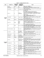
Страница 28: ...040839 001 Rev G HJW10 www energy ca gov Certified FDD Product California Title 24 Part 6 Table 8 Economizer Module Left Hand Terminal Blocks LABEL TYPE DESCRIPTION Top Left Terminal Block MAT MAT 20k...

Страница 29: ...D display and a 4 button keypad on the front of the economizer controller Keypad Use the four navigation buttons see Fig 48 to scroll through the menus and menu items select menu items and to change p...

Страница 30: ...ETUP ADVANCED SETUP CHECKOUT ALARMS NOTE Some parameters in the menus use the letters MA or MAT indicating a mixed air temperature sensor location before the cooling coil This unit application has the...

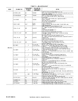
Страница 31: ..._ F if not connected short or out of range DA TEMP _ _ _ F 0 F to 140 F 18 C to 60 C DISCHARGE AIR TEMPERATURE after Heating section Displays when Discharge Air sensor is connected and displays measu...

Страница 32: ...2 8 V 2 to 10 Vdc DCV MAXIMUM DAMPER POSITION Displays only if a CO2 sensor is connected Used for Vbz ventilation max cfm setpoint Displays 2 to 10 V if 3 sensors RA OA and MA In AUTO mode dampers con...

Страница 33: ...SET 45 F 35 F to 55 F 2 C to 13 C Incremented by 10 F SUPPLY AIR TEMPERATURE LOW LIMIT Temperature to achieve Freeze Protection close damper and alarm if temperature falls below setup value FREEZE POS...

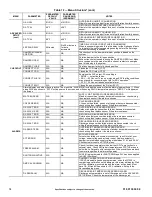
Страница 34: ...r has failed or become disconnected check wiring then replace sensor if the alarm continues CO2 SENS ERR N A N A CO2 SENSOR ERROR CO2 sensor has failed gone out of range or become disconnected check w...

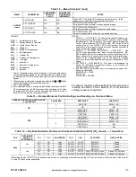
Страница 35: ...tion settings and checkout menu readings see Table 13 See Tables 14 21 for dry bulb and enthalpy sequence of operation With stage 3 delay STG3 DLY in Advanced setup menu second stage of mechanical coo...

Страница 36: ...v On 0 v Off VENTMIN to VENTMAX Closed On On High 24 v On 24 v On VENTMIN to VENTMAX Closed Yes Off Off High 0 v Off 0 v Off VENTMIN to VENTMAX Closed On Off High 0 v Off 0 v Off VENTMIN to Full Open...

Страница 37: ...O Y2 O OCCUPIED UNOCCUPIED None No Off Off Low 0 v Off 0 v Off MIN POS L Closed On Off Low 24 v On 0 v Off MIN POS L Closed On On High 24 v On 24 v On MIN POS H Closed Yes Off Off Low 0 v Off 0 v Off...

Страница 38: ...y for differential enthalpy The high limit boundary is ES1 when there are no stages of mechanical cooling energized and HL high limit when a compressor stage is energized Table 21 Enthalpy Operation w...

Страница 39: ...ly items that are configured are shown in the Checkout menu NOTE For information about menu navigation and use of the keypad see Interface Overview on page 29 To perform a Checkout test 1 Scroll to th...

Страница 40: ...mpling inlet to the sampling tube on the basepan 2 SPEED INDOOR FAN MOTOR SYSTEM WITH VARI ABLE FREQUENCY DRIVE FACTORY INSTALLED OPTION For details on operating RHH 2 stage cooling units equipped wit...

Страница 41: ...he belt span length by 1 64 For example if the belt span length is 32 inches 32 x 1 64 1 2 inch deflection BELT FORCE DEFLECTION METHOD Check the belt tension with a spring force belt force deflec tio...

Страница 42: ...ners www hvacpartners com TORQUE ALL SHEAVE SET SCREWS TO 110 130 in lbs SET SCREW SET SCREW STRAIGHT EDGE BELT SPAN BELT DEFLECTION FORCE SEE TABLE 1 DEFLECTION BELT SPAN 64 TABLE 1 TABLE 2 BELT CROS...

Страница 43: ...opeller for location in housing orifice and verify setscrew is tight Y N _____ Verify that fan sheaves are aligned and belts are properly tensioned Y N _____ Verify that scroll compressors are rotatin...

Страница 44: ...L2 _____________ L3 _____________ TEMPERATURES Outdoor air Temperature _____________ F DB Dry Bulb Return air Temperature _____________ F DB _____________ F Wb Wet Bulb Cooling Supply Air Temperature...

Отзывы: