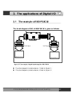
The circuit diagram of external device 1 is given as follows:
DN-37 I/O CONNECTOR BLOCK
CE
COM
Power Supply
+5.00 V
POWER
On
OFF
ICP DAS
Super 2
Vlotage Output
1
19
20
37
R1
R2
R3
R4
R5
R6
R7
R8
R9
R10
R11
R12
R13
R14
R15
R16
LED 1
LED 2
LED 3
LED 4
LED 5
LED 6
LED 7
LED 8
LED 9
LED 10
LED 11
LED 12
LED 13
LED 14
LED 15
LED 16
R17
R18
R19
R20
R21
R22
R23
R24
LED 17
LED 18
LED 19
LED 20
LED 21
LED 22
LED 23
LED 24
LED 25
LED 26
LED 27
LED 28
LED 29
LED 30
LED 31
LED 32
R26
R27
R27
R28
R29
R30
R31
R32
From the CON1 of ISO-C64
Figure 3-10: The circuit diagram of external device 1 for the digital outputs of ISO-C64
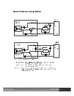
The resistor of R1~R32 are 330 Ohm.
The LED 1~LED 32 are light emitting diode.
The pin-1/20 are the GND signal of DO_0~DO_15 / DO_16~DO_31.
The pin-18/37 are the voltage (+) signal of DO_0~DO_15 /
DO_16~DO_31 (Input 5 V
DC
~24 V
DC
).
ISO
-P32C32/P32S32W/P64/C64 User Manual (Ver.1.9, Oct. 2011, IMH-000-19)
47


