background image


ISO

-P32C32/P32S32W/P64/C64 User Manual (Ver.1.9, Oct. 2011, IMH-000-19)   


33


2.6.1   Sample D/O Architecture 


Содержание ISO-P32C32

Страница 1: ...s the right to change this manual at any time without notice The information furnished by ICP DAS is believed to be accurate and reliable However no responsibility is assumed by ICP DAS for its use no...

Страница 2: ...3 1 Jumper setting 18 2 3 2 I O Base Address Setting 18 2 3 3 I O Register Address 21 2 4 ISO C64 BOARD LAYOUT 22 2 4 1 I O Base Address Setting 23 2 4 2 I O Register Address 26 2 5 ISOLATED D I ARCHI...

Страница 3: ...THE EXAMPLE OF ISO P32C32 40 3 2 THE EXAMPLE OF ISO P64 43 3 3 THE EXAMPLE OF ISO C64 46 4 DEMO PROGRAM 49 4 1 DEMO1 D O FOR ISO P32C32 P32S32W 49 4 2 DEMO2 D I FOR ISO P32C32 P32S32W 50 4 3 DEMO3 D I...

Страница 4: ...lity Photo isolated current Input Voltage Logic 0 DC 0 1 V Logic 1 DC 9 24 V Input Impedance 3 K 0 5 W Response Speed 4 kHz Typical Digital Output Isolation Voltage 3750 Vrms Using external power Chan...

Страница 5: ...r External Voltage 5 30 VDC max 500 mA for one high driving channel 100 duty 500 mA for all high driving channels 100 duty The GND pins all must be connected with GND of External Power Output Capabili...

Страница 6: ...0 70 C Humidity 5 85 RH non condensing 1 1 4 ISO C64 Model Name ISO C64 Digital Output Isolation Voltage 3750 Vrms Using external power Channels 64 Compatibility Sink Open Collector External Voltage 5...

Страница 7: ...32 P32S32W ISA bus D I of 32 bit D O of 32 bit ISO P64 ISA bus D I of 64 bit ISO C64 ISA bus D O of 64 bit 1 3 Options ADP 37 PCI extender 50 pin OPTO 22 header to DB 37 for PCI Bus I O boards ADP 50...

Страница 8: ...tial information is given in the Quick Start Guide including Where to get the software driver demo programs and other resources How to install the software How to test the card Attention If any of the...

Страница 9: ...O channel 16 31 CON2 37 PIN D sub connector for D I O channel 0 15 JP1 CON1 select internal external power JP2 CON2 select internal external power JP3 Interrupt levels selection ISO P32C32 provides I...

Страница 10: ...DI O Channel DI DO Channel Power Ground Isolation Bank 1 DI_0 15 CON1 Pin1 DO_0 3 High drive for 500 mA sink current NPN CON1 Pin18 Pin19 Isolation Bank 2 DO_4 15 Low drive for 100 mA sink current NP...

Страница 11: ...I channel 16 of CON1 Select IRQ one of the 9 10 11 12 14 15 for D I channel 0 of CON2 Usage Step 1 Select IRQ 3 4 5 6 7 for channel 16 Step 2 Select IRQ 9 10 11 12 14 15 for channel 0 Step 3 Input in...

Страница 12: ...rcuit diagram of IRQ for ISO P32C32 P32S32W board External signal inupt to channel 0 or channel 16 Interrupt happend to rising edge Figure 2 3 Interrupt happened to rising edge ISO P32C32 P32S32W P64...

Страница 13: ...BASE ADDRESS ON 1 2 3 4 5 6 SW1 Default Base Address 200 Hex For Example How to select 2 0 0 Hex OFF 1 ON 0 2 0 0 ON ON ON ON ON ON 0 0 0 0 0 0 1 1 A8 2 A7 3 A6 4 A5 5 A4 6 A3 The detail SW1 base add...

Страница 14: ...268 ON ON OFF OFF ON OFF 270 ON ON OFF OFF OFF ON 278 ON ON OFF OFF OFF OFF 280 ON OFF ON ON ON ON 288 ON OFF ON ON ON OFF 290 ON OFF ON ON OFF ON 298 ON OFF ON ON OFF OFF 2A0 ON OFF ON OFF ON ON 2A8...

Страница 15: ...FF OFF ON ON 368 OFF ON OFF OFF ON OFF 370 OFF ON OFF OFF OFF ON 378 OFF ON OFF OFF OFF OFF 380 OFF OFF ON ON ON ON 388 OFF OFF ON ON ON OFF 390 OFF OFF ON ON OFF ON 398 OFF OFF ON ON OFF OFF 3A0 OFF...

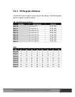
Страница 16: ...0 7 D O Channel 0 7 CON 2 Base 1 D I Channel 8 15 D O Channel 8 15 CON 2 Base 2 D I Channel 16 23 D O Channel 16 23 CON 1 Base 3 D I Channel 14 31 D O Channel 14 31 CON 1 Read Write Base 0 Bit 7 6 5...

Страница 17: ...nal power for DI_47 DI_32 3000 V isolation JP4 select internal external power for DI_63 DI_48 3000 V isolation Isolation bank 1 DI_0 DI_15 Power CON1_18 Ground CON1_1 Isolation bank 2 DI_16 DI_31 Powe...

Страница 18: ...ON 1 2 3 4 5 6 BASE ADDRESS SW1 Default Base Address 200 Hex For Example How to select 2 0 0 Hex OFF 1 ON 0 2 0 0 ON ON ON ON ON ON 0 0 0 0 0 0 1 1 A8 2 A7 3 A6 4 A5 5 A4 6 A3 The detail SW1 base add...

Страница 19: ...ON OFF 270 ON ON OFF OFF OFF ON 278 ON ON OFF OFF OFF OFF 280 ON OFF ON ON ON ON 288 ON OFF ON ON ON OFF 290 ON OFF ON ON OFF ON 298 ON OFF ON ON OFF OFF 2A0 ON OFF ON OFF ON ON 2A8 ON OFF ON OFF ON...

Страница 20: ...368 OFF ON OFF OFF ON OFF 370 OFF ON OFF OFF OFF ON 378 OFF ON OFF OFF OFF OFF 380 OFF OFF ON ON ON ON 388 OFF OFF ON ON ON OFF 390 OFF OFF ON ON OFF ON 398 OFF OFF ON ON OFF OFF 3A0 OFF OFF ON OFF ON...

Страница 21: ...e 3 Channel 24 31 Read Only Base 4 Channel 32 39 Read Only Base 5 Channel 40 47 Read Only Base 6 Channel 48 55 Read Only Base 7 Channel 56 63 Read Only Read Bit D7 D6 D5 D4 D3 D2 D1 D0 Base 0 7 6 5 4...

Страница 22: ...DO_31 DO_16 LED 3 power indicator for DO_47 DO_32 LED 4 power indicator for DO_63 DO_48 Isolation bank 1 DO_0 DO_15 Power CON1_18 Ground CON1_1 Isolation bank 2 DO_16 DO_31 Power CON1_37 Ground CON1_...

Страница 23: ...ress 200 Hex For Example How to select 2 0 0 Hex OFF 1 ON 0 2 0 0 ON ON ON ON ON ON 0 0 0 0 0 0 1 1 A8 2 A7 3 A6 4 A5 5 A4 6 A3 The detail SW1 base addresses setting Please refer to ISO C64 Base Addre...

Страница 24: ...ON ON OFF OFF OFF ON 278 ON ON OFF OFF OFF OFF 280 ON OFF ON ON ON ON 288 ON OFF ON ON ON OFF 290 ON OFF ON ON OFF ON 298 ON OFF ON ON OFF OFF 2A0 ON OFF ON OFF ON ON 2A8 ON OFF ON OFF ON OFF 2B0 ON O...

Страница 25: ...FF OFF ON OFF 370 OFF ON OFF OFF OFF ON 378 OFF ON OFF OFF OFF OFF 380 OFF OFF ON ON ON ON 388 OFF OFF ON ON ON OFF 390 OFF OFF ON ON OFF ON 398 OFF OFF ON ON OFF OFF 3A0 OFF OFF ON OFF ON ON 3A8 OFF...

Страница 26: ...3 Channel 24 31 Write Only Base 4 Channel 32 39 Write Only Base 5 Channel 40 47 Write Only Base 6 Channel 48 55 Write Only Base 7 Channel 56 63 Write Only Write Bit D7 D6 D5 D4 D3 D2 D1 D0 Base 0 7 6...

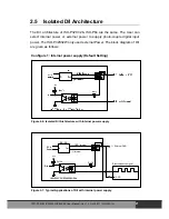
Страница 27: ...he block diagram of D I are given as follows Configure 1 Internal power supply Default Setting Figure 2 6 Isolated D I Architecture with internal power supply R 3K D in Vcc R 10k External source signa...

Страница 28: ...ternal power supply R 3K D in Vcc R 10k DC DC PC s Power In Out Internal GND Internal ISO P32C32 P32S32W P64 D Input External External Power External GND Figure 2 8 Isolated D I Architecture with exte...

Страница 29: ...r R 3K DI 0 Vcc R 4 7k D DC DC PC s Power In Out Internal GND Internal ISO P32C32 ISO P64 External GND R 3K R 4 7k D R 3K R 4 7k D DI 1 DI 2 Switch 0 Switch 2 Switch 31 Vcc Vcc ISO P32C32 P32S32W P64...

Страница 30: ...2 5 2 Sample D I Architecture for External Power ISO P32C32 P32S32W P64 C64 User Manual Ver 1 9 Oct 2011 IMH 000 19 30...

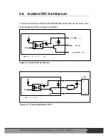
Страница 31: ...ecture of ISO P32C32 P32S32W ISO C64 are the same The block diagrams of D O are given as follows Figure 2 10 Isolated D O Architecture Figure 2 11 Typical Applications of D O ISO P32C32 P32S32W P64 C6...

Страница 32: ...R1 R2 R32 are current limit resistors They must be designed to let I1 I2 I32 100 mA for ISO P32C32 C64 I1 4 I17 20 500 mA for ISO P32S32W 3 If the internal resistance of external device is large enou...

Страница 33: ...ISO P32C32 P32S32W P64 C64 User Manual Ver 1 9 Oct 2011 IMH 000 19 33 2 6 1 Sample D O Architecture...

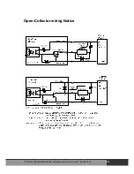
Страница 34: ...Open Collector wiring Notice ISO P32C32 P32S32W P64 C64 User Manual Ver 1 9 Oct 2011 IMH 000 19 34...

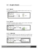
Страница 35: ...is a general purpose daughter board for DB 37 with DIN Rail Mounting It is designed for easy wire connection DN 37 2 7 3 DB 8125 The DB 8125 is a general purpose screw terminal board It is designed fo...

Страница 36: ...DI 25 DI 16 31 DO 16 31 DO 16 DO 17 DO 18 DO 19 DO 20 DO 21 DO 22 DO 23 DO 24 DO 25 DO 26 DO 27 DO 28 DO 29 DO 30 DO 31 DO 16 31 External Power GND External Power GND External Power External Power GND...

Страница 37: ...DO 23 DO 24 DO 25 DO 26 DO 27 DO 28 DO 29 DO 30 DO 31 External Power GND External Power GND DO 16 for High drive DO 16 for High drive DO 17 for High drive DO 18 for High drive DO 19 for High drive GN...

Страница 38: ...32 47 DI 48 DI 49 DI 50 DI 51 DI 52 DI 53 DI 54 DI 55 DI 56 DI 57 DI 58 DI 59 DI 60 DI 61 DI 62 DI 63 DI 48 63 External Power GND External Power GND External Power External Power DB 40 Pin conversion...

Страница 39: ...CON2 D O External Power DO 48 DO 54 DO 53 DO 52 DO 51 DO 50 DO 49 DO 55 DO 56 N C N C CON2 D O External Power GND CON2 D O External Power GND CON2 D I Power CON2 D I Power N C Extension Cable DB 40 Pi...

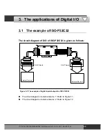
Страница 40: ...Cable ISA BUS ISO P32C32 CON2 DB 37 CON1 40 PIN DC DC 1 DC DC 2 JP1 JP2 LED1 LED2 LED3 LED4 DN 37 Board DN 37 Board Figure 3 1 The example of digital inputs outputs for ISO P32C32 The circuit diagram...

Страница 41: ...P32C32 Figure 3 2 The D I O of CON1 of ISO P32C32 The D I of CON2 of ISO P32C32 for internal power DN 37 I O CONNECTOR BLOCK CE 1 19 20 37 GND GND From the CON2 of ISO P32C32 Figure 3 3 The D I O of...

Страница 42: ...2C32 The interrupt input of circuit diagram 2 of ISO P32C32 is given as follows Figure 3 5 The interrupt input for ISO P32C32 DN 37 I O CONNECTOR BLOCK CE 1 19 20 37 2 21 DN 37 I O CONNECTOR BLOCK CE...

Страница 43: ...P64 is given as follows External Device 1 External Device 2 External Cable ISA BUS ISO P64 CON1 DB 37 CON2 40 PIN DC DC 1 J1 J2 J3 J4 DC DC2 Figure 3 6 The example of digital inputs for ISO P64 The c...

Страница 44: ...10 11 12 13 14 15 16 9 7 8 6 5 ON ON 17 18 19 20 26 27 28 29 30 31 32 25 23 24 22 21 From the CON1 of ISO P64 Figure 3 7 The circuit diagram of external device 2 for the digital inputs of ISO P64 The...

Страница 45: ...42 43 44 45 46 47 48 41 39 40 38 37 ON ON 49 50 51 52 58 59 60 61 62 63 64 57 55 56 54 53 From the CON2 of ISO P64 Figure 3 8 The circuit diagram of external device 2 for the digital inputs of ISO P64...

Страница 46: ...al Cable ISA BUS ISO C64 CON1 DB 37 CON2 40 PIN DN 37 I O CONNECTOR DN 37 I O CONNECTOR Figure 3 9 The example of digital outputs for ISO C64 The circuit diagram of external device 1 Refer to Figure 1...

Страница 47: ...R23 R24 LED 17 LED 18 LED 19 LED 20 LED 21 LED 22 LED 23 LED 24 LED 25 LED 26 LED 27 LED 28 LED 29 LED 30 LED 31 LED 32 R26 R27 R27 R28 R29 R30 R31 R32 From the CON1 of ISO C64 Figure 3 10 The circuit...

Страница 48: ...53 R54 R55 R56 LED 49 LED 50 LED 51 LED 52 LED 53 LED 54 LED 55 LED 56 LED 57 LED 58 LED 59 LED 60 LED 61 LED 62 LED 63 LED 64 R57 R58 R59 R60 R61 R62 R63 R64 From the CON2 of ISO C64 Figure 3 11 The...

Страница 49: ...in char c unsigned char i clrscr initial value outp wBase 0 0x00 outp wBase 1 0x00 outp wBase 2 0x00 outp wBase 3 0x00 while 1 printf n n Digital output of ISO P32C32 for i 1 i 0x80 i i 1 outp wBase 0...

Страница 50: ...input from DI_0 to DI_31 while 1 for printf n n Digital input of ISO P32C32 j1 inp wBase 0 0xff DI_07 to DI_00 of CON2 j2 inp wBase 1 0xff DI_15 to DI_08 of CON2 j3 inp wBase 2 0xff DI_23 to DI_16 of...

Страница 51: ...se 3 i DO_31 to DO_24 of CON1 sleep 1 j1 inp wBase 0 0xff DI_07 to DI_00 of CON2 j2 inp wBase 1 0xff DI_15 to DI_08 of CON2 j3 inp wBase 2 0xff DI_23 to DI_16 of CON1 j4 inp wBase 3 0xff DI_31 to DI_2...

Страница 52: ...P64 C64 User Manual Ver 1 9 Oct 2011 IMH 000 19 52 if i j1 i j2 i j3 i j4 printf The Digital I O test of PISO P32C32 by itself OK n if i 0x80 i 0x01 break if kbhit 0 c getch if c q c Q c 27 return de...

Страница 53: ...for Interrupt of ISO P32C32 endl cout endl cout Wire connection endl cout Setting JP1 JP2 to Internal Power endl cout Connect DO0 with DI0 CON2 Pin21 with CON2 Pin2 endl cout Connect DO16 with DI16 CO...

Страница 54: ...upt Source to enable Interrupt DIO_OutputByte wBase 2 1 Sleep 100 DIO_OutputByte wBase 2 0 Sleep 100 Make the Output Channel 0 to high then low to generate the interrupt signal for IRQ9 10 11 12 14 15...

Страница 55: ...0 r2 inp wBase 1 DI_15 to DI_08 r3 inp wBase 2 DI_23 to DI_16 r4 inp wBase 3 DI_31 to DI_24 r5 inp wBase 4 DI_39 to DI_32 r6 inp wBase 5 DI_47 to DI_40 r7 inp wBase 6 DI_55 to DI_48 r8 inp wBase 7 DI_...

Страница 56: ...ase 1 i DO_15 to DO_08 outp wBase 2 i DO_23 to DO_16 outp wBase 3 i DO_31 to DO_24 outp wBase 4 i DO_39 to DO_32 outp wBase 5 i DO_47 to DO_40 outp wBase 6 i DO_55 to DO_48 outp wBase 7 i DO_63 to DO_...

Отзывы: