


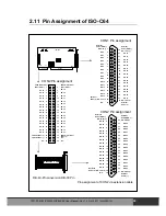


3.3 The example of ISO-C64
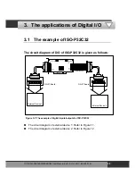
The circuit diagram of D/O for ISO-P32C32 is given as
follows:
External Device 1
External Device 2
External Cable
ISA BUS
ISO-C64
CON1
DB-37
CON2
40-PIN
DN-37 I/O CONNECTOR
DN-37 I/O CONNECTOR
Figure 3-9: The example of digital outputs for ISO-C64
The circuit diagram of external device 1: Refer to Figure 17.
The circuit diagram of external device 2: Refer to Figure 18.
ISO
-P32C32/P32S32W/P64/C64 User Manual (Ver.1.9, Oct. 2011, IMH-000-19)
46