2.3 ISO-P64 Board Layout
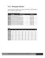
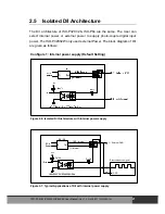
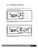
The board layout of ISO-P64 is given as follows:
ISA BUS
ON
1 2 3 4 5 6
JP4
Internal
External
External
Internal
JP2
ISA BUS
ISO-P64
1
2
6
5
1
2
6
5
1
2
6
5
1
2
6
5
JP3
JP2
JP1
CON1
CON2
SW1
Figure 2-5: Board layout of ISO-P64
JP1: select internal/external power for DI_0 ~ DI_15 (3000 V isolation)
JP2: select internal/external power for DI_16 ~ DI_31 (3000 V isolation)
JP3: select internal/external power for DI_47 ~ DI_32 (3000 V isolation)
JP4: select internal/external power for DI_63 ~ DI_48 (3000 V isolation)
Isolation bank 1: DI_0 ~ DI_15, Power=CON1_18, Ground=CON1_1
Isolation bank 2: DI_16 ~ DI_31, Power=CON1_37, Ground=CON1_20
Isolation bank 3: DI_32 ~ DI_47, Power=CON2_18, Ground=CON2_1
Isolation bank 4: DI_48 ~ DI_63, Power=CON2_37, Ground=CON2_20
All these four banks are fully isolated from each other.
The DC/DC1 is used to provide the internal power supply for bank1 & bank2.
The DC/DC2 is used to provide the internal power supply for bank3 & bank4.
ISO
-P32C32/P32S32W/P64/C64 User Manual (Ver.1.9, Oct. 2011, IMH-000-19)
17


