


Maintenance, troubleshooting, spare parts and dismantling
iDRY iRDP CT 20-500
35
The internal heat
protection of the
compressor has been
activated
Check which of the following reasons has caused the activation:
1. Excessive thermal load – restore the standard operating conditions.
2. The inlet air is too hot – restore the nominal conditions.
3. The ambient temperature is too high or the room aeration is insufficient – provide proper
ventilation.
4. The condenser unit is dirty – clean it.
5. The fan does not work – see specific point.
6. If ESS=NO (see section 8.12.7) – The hot gas bypass valve is out of setting – contact a ICP
service technician to restore nominal setting.
7. The solenoid valve EVL is not operating correctly - see specific point.
8. There is a leak in the refrigerant circuit – please contact a ICP service technician.
wait 30 minutes and then retry.
The solenoid valve
EVL or EVH doesn’t
operate correctly
The solenoid valve is not activated and there is no voltage to the coil – verify the
electric wiring.
The solenoid valve is not activated and there is no voltage to the coil – the internal
relay of DMC51 is faulty – replace DMC51.
The solenoid valve is not activated and there is voltage to the coil – the coil is faulty –
replace it.
The solenoid valve is not activated and there is voltage to the coil – the solenoid
valve is jammed - contact a ICP service technician for the replacement.
The solenoid valve is always activated and there is always voltage to the coil – verify
the electric wiring
The solenoid valve is always activated and there is always voltage to the coil – the
internal relay of DMC51 is faulty – replace DMC51.
The solenoid valve is always activated and there is no voltage to the coil – the
solenoid valve is jammed - contact a ICP service technician for the replacement.
If installed: the HPS
high-pressure switch
has been activated.
Check which of the following reasons has caused the activation:
1. The ambient temperature is too high or the room aeration is insufficient – provide proper
ventilation.
2. The condenser is dirty – clean it.
3. The fan does not work – see specific point.
4. The solenoid valve EVL is not operating correctly - see specific point
Reset the pressure switch by pressing the button on the switch itself – check the proper
operation of the dryer.
The HPS pressure switch is faulty – contact a ICP service technician for the replacement.
If
installed:
the LPS low-pressure
switch has been
activated.
There is a leak in the refrigerant circuit – please contact a ICP service technician.
The solenoid valve EVL is not operating correctly - see specific point
The solenoid valve EVH is not operating correctly - see specific point
The hot-gas bypass valve is faulty – contact a ICP service technician for the replacement
The pressure switch reset automatically when normal conditions are restored – check the
proper operation of the dryer.
If T2 installed:
the alarm
(Hdt)
compressor outlet
temperature too high –
has been triggered.
Check which of the following reasons has caused the alarm:
1. Excessive thermal load – restore the standard operating conditions.
2. The inlet air is too hot – restore the nominal conditions.
3. The ambient temperature is too high or the room aeration is insufficient – provide proper
ventilation.
4. The condenser unit is dirty – clean it.
5. The fan does not work – see specific point.
6. The fan is always ON – verify the electric wiring, verify the setting of PV pressure switch or
the PV pressure switch is faulty – contact a ICP service technician to replace it
7. The T2 sensor is faulty – replace it
8. If ESS=NO (see section 8.12.7) – The hot gas bypass valve is out of setting – contact a ICP
service technician to restore nominal setting.
9. The solenoid valve EVL is not operating correctly - see specific point
10. There is a leak in the refrigerant circuit – please contact a ICP service technician.
Содержание iDRY iRDP CT 100
Страница 28: ...Technical data 28 iDRY iRDP CT 20 500 11 Technical data 11 1 Technical data iDRY iRDP CT 20 200 1 1 115 60...
Страница 29: ...Technical data iDRY iRDP CT 20 500 29 11 2 Technical data iDRY iRDP CT 20 500 2 1 230 60...
Страница 30: ...Technical data 30 iDRY iRDP CT 20 500 11 3 Technical data iDRY iRDP CT 200 500 3phase 4 3 460 60...
Страница 38: ...Maintenance troubleshooting spare parts and dismantling 38 iDRY iRDP CT 20 500...
Страница 39: ...Maintenance troubleshooting spare parts and dismantling iDRY iRDP CT 20 500 39...
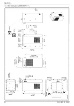
Страница 42: ...Appendices 42 iDRY iRDP CT 20 500 13 1 2 Dryer dimensions iDRY iRDP CT 75...
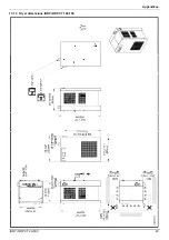
Страница 43: ...Appendices iDRY iRDP CT 20 500 43 13 1 3 Dryer dimensions iDRY iRDP CT 100 150...
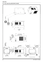
Страница 44: ...Appendices 44 iDRY iRDP CT 20 500 13 1 4 Dryer dimensions iDRY iRDP CT 200 250...
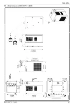
Страница 45: ...Appendices iDRY iRDP CT 20 500 45 13 1 5 Dryer dimensions iDRY iRDP CT 300 350...
Страница 46: ...Appendices 46 iDRY iRDP CT 20 500 13 1 6 Dryer dimensions iDRY iRDP CT 400 500...
Страница 47: ...Appendices iDRY iRDP CT 20 500 47 13 1 7 Dryer dimensions iDRY iRDP CT 200 250 3phase...
Страница 48: ...Appendices 48 iDRY iRDP CT 20 500 13 1 8 Dryer dimensions iDRY iRDP CT 300 350 3phase...
Страница 49: ...Appendices iDRY iRDP CT 20 500 49 13 1 9 Dryer dimensions iDRY iRDP CT 400 500 3phase...
Страница 51: ...Appendices iDRY iRDP CT 20 500 51 13 2 2 Exploded diagram iDRY iRDP CT 20 30...
Страница 52: ...Appendices 52 iDRY iRDP CT 20 500 13 2 3 Exploded diagram iDRY iRDP CT 50...
Страница 53: ...Appendices iDRY iRDP CT 20 500 53 13 2 4 Exploded diagram iDRY iRDP CT 75...
Страница 54: ...Appendices 54 iDRY iRDP CT 20 500 13 2 5 Exploded diagram iDRY iRDP CT 100...
Страница 55: ...Appendices iDRY iRDP CT 20 500 55 13 2 6 Exploded diagram iDRY iRDP CT 125 150...
Страница 56: ...Appendices 56 iDRY iRDP CT 20 500 13 2 7 Exploded diagram iDRY iRDP CT 200 250...
Страница 57: ...Appendices iDRY iRDP CT 20 500 57 13 2 8 Exploded diagram iDRY iRDP CT 300 350...
Страница 58: ...Appendices 58 iDRY iRDP CT 20 500 13 2 9 Exploded diagram iDRY iRDP CT 400 500...
Страница 59: ...Appendices iDRY iRDP CT 20 500 59 13 2 10 Exploded diagram iDRY iRDP CT 200 250 3phase...
Страница 60: ...Appendices 60 iDRY iRDP CT 20 500 13 2 11 Exploded diagram iDRY iRDP CT 300 350 3phase...
Страница 61: ...Appendices iDRY iRDP CT 20 500 61 13 2 12 Exploded diagram iDRY iRDP CT 400 500 3phase...
Страница 71: ...Appendices iDRY iRDP CT 20 500 71...
Страница 72: ...Independent Compressor Partners LLC Jeffersonville IN 47131 www icompressorpartners com 7425MUM289_EN_2014 09...


