Maintenance, troubleshooting, spare parts and dismantling
36
iDRY iRDP CT 20-500
The
alarm
(toC),
- ON/OFF cycles of the
compressor too
frequent –
has been triggered
If ESS=YES (see section 8.12.7) - The refrigerating compressor must remain ON for
a minimum time (approx. 6 minutes) within which, if necessary, DMC51 will activate
the solenoid EVH that enables the operation of the hot gas by-pass valve. To avoid
freezing, if the DewPoint drops too low in despite the hot gas by-pass valve is in
operation, the compressor is switched OFF before its minimum ON time (approx. 6
minutes). If this happens too many times the alarm
(TOC) is activated to avoid
damaging the compressor.
Check which of the following reasons has caused the alarm:
1. The inlet air is too cold – restore the nominal conditions.
2. The ambient temperature is too low - restore the nominal conditions.
3. The hot gas bypass valve is out of setting – contact a ICP service technician to
restore nominal setting.
4. The solenoid valve EVH is not operating correctly - see specific point.
The
alarm
(ICE)
has been triggered
Check which of the following reasons has caused the alarm:
1. The inlet air is too cold – restore the nominal conditions.
2. The ambient temperature is too low - restore the nominal conditions.
3. The refrigerating compressor is always ON, even though the led
is OFF – verify
the electric wiring or KC relay (if installed) is faulty – replace it.
DMC51 - The LED
is ON or flashing
With
LED flashing: one or more alarms are active and the display shows
and the active alarms.
With
LED lit: one or more alarms are waiting to be reset and the display shows
and the alarms that are no longer active but not yet reset.
The alarms are displayed by the following messages:
1.
: LP - LPS pressure switch activated (low pressure) – see specific paragraph.
2.
: Hdt - Compressor discharge temperature too high (probe T2) – see specific
paragraph.
3.
: ICE - Temperature inside the exchanger too low (probe T1) – the dew point is
too low – see specific paragraph.
4.
: toC – ON/OFF cycles of the compressor too frequent – Compressor has been
repeatedly switched OFF before its minimum ON time (approx. 6 minutes) - see
specific paragraph.
5.
: PF1 - Failure temperature probe T1 (DewPoint) – verify electric wiring and/or
replace probe.
6.
: PF2 – Failure temperature probe T2 (compressor outlet) – If probe T2 installed :
verify electric wiring and/or replace probe; If probe T2 not installed : verify electric
wiring and/or replace the resistor R.
NOTE: after solving the problem, the alarms must be reset (simultaneously press
the
Set
+
buttons for three seconds).
DMC51 - The LED
is ON or flashing
With
LED flashing, one or more service warnings are active.
With
LED lit: one or more service warnings are waiting to be reset. The display
shows the dew point temperature and the active or not reset service warning.
The service warnings are displayed by the following messages:
1.
: Hdp - Dew point too high (higher than the set HdS value) – see specific
paragraph.
2.
: Ldp - Dew point too low – see specific paragraph.
3.
: SrV - Service - maintenance notification time expired (parameter SrV) – carry
out the scheduled maintenance and reset the hour meter.
NOTE: after solving the problem, the service warnings must be reset
(simultaneously press the
Set
+
buttons for three seconds)
.
Содержание iDRY iRDP CT 100
Страница 28: ...Technical data 28 iDRY iRDP CT 20 500 11 Technical data 11 1 Technical data iDRY iRDP CT 20 200 1 1 115 60...
Страница 29: ...Technical data iDRY iRDP CT 20 500 29 11 2 Technical data iDRY iRDP CT 20 500 2 1 230 60...
Страница 30: ...Technical data 30 iDRY iRDP CT 20 500 11 3 Technical data iDRY iRDP CT 200 500 3phase 4 3 460 60...
Страница 38: ...Maintenance troubleshooting spare parts and dismantling 38 iDRY iRDP CT 20 500...
Страница 39: ...Maintenance troubleshooting spare parts and dismantling iDRY iRDP CT 20 500 39...
Страница 42: ...Appendices 42 iDRY iRDP CT 20 500 13 1 2 Dryer dimensions iDRY iRDP CT 75...
Страница 43: ...Appendices iDRY iRDP CT 20 500 43 13 1 3 Dryer dimensions iDRY iRDP CT 100 150...
Страница 44: ...Appendices 44 iDRY iRDP CT 20 500 13 1 4 Dryer dimensions iDRY iRDP CT 200 250...
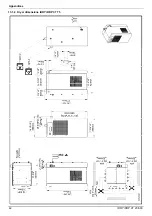
Страница 45: ...Appendices iDRY iRDP CT 20 500 45 13 1 5 Dryer dimensions iDRY iRDP CT 300 350...
Страница 46: ...Appendices 46 iDRY iRDP CT 20 500 13 1 6 Dryer dimensions iDRY iRDP CT 400 500...
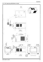
Страница 47: ...Appendices iDRY iRDP CT 20 500 47 13 1 7 Dryer dimensions iDRY iRDP CT 200 250 3phase...
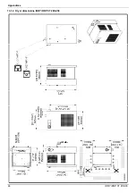
Страница 48: ...Appendices 48 iDRY iRDP CT 20 500 13 1 8 Dryer dimensions iDRY iRDP CT 300 350 3phase...
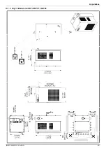
Страница 49: ...Appendices iDRY iRDP CT 20 500 49 13 1 9 Dryer dimensions iDRY iRDP CT 400 500 3phase...
Страница 51: ...Appendices iDRY iRDP CT 20 500 51 13 2 2 Exploded diagram iDRY iRDP CT 20 30...
Страница 52: ...Appendices 52 iDRY iRDP CT 20 500 13 2 3 Exploded diagram iDRY iRDP CT 50...
Страница 53: ...Appendices iDRY iRDP CT 20 500 53 13 2 4 Exploded diagram iDRY iRDP CT 75...
Страница 54: ...Appendices 54 iDRY iRDP CT 20 500 13 2 5 Exploded diagram iDRY iRDP CT 100...
Страница 55: ...Appendices iDRY iRDP CT 20 500 55 13 2 6 Exploded diagram iDRY iRDP CT 125 150...
Страница 56: ...Appendices 56 iDRY iRDP CT 20 500 13 2 7 Exploded diagram iDRY iRDP CT 200 250...
Страница 57: ...Appendices iDRY iRDP CT 20 500 57 13 2 8 Exploded diagram iDRY iRDP CT 300 350...
Страница 58: ...Appendices 58 iDRY iRDP CT 20 500 13 2 9 Exploded diagram iDRY iRDP CT 400 500...
Страница 59: ...Appendices iDRY iRDP CT 20 500 59 13 2 10 Exploded diagram iDRY iRDP CT 200 250 3phase...
Страница 60: ...Appendices 60 iDRY iRDP CT 20 500 13 2 11 Exploded diagram iDRY iRDP CT 300 350 3phase...
Страница 61: ...Appendices iDRY iRDP CT 20 500 61 13 2 12 Exploded diagram iDRY iRDP CT 400 500 3phase...
Страница 71: ...Appendices iDRY iRDP CT 20 500 71...
Страница 72: ...Independent Compressor Partners LLC Jeffersonville IN 47131 www icompressorpartners com 7425MUM289_EN_2014 09...


