
GW-7553-B / GW-7553-M PROFIBUS/Modbus TCP Gateway User Manual
(Version 1.35, May/2017)
PAGE: 43
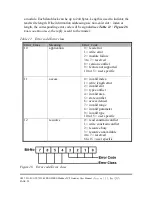
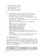
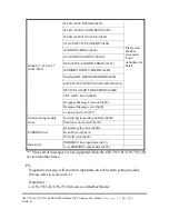
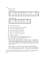
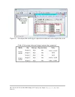
Table 15 Input data area
Module
Byte
Data
Description
System setting module
(diagnostic message)
0
The number of Diagnostic messages
1
00or05
Fixed value(The value is00 when byte 0 is 0,
The value is 05 when byte 0 is not 0)
2
00orA0
Fixed value(The value is00 when byte 0 is 0,
The value isA0 when byte 0 is not 0)
3
Message(refer to Table 14)
4
00
Fixed value
5
Description(refer to Table 14)
Input module
6~239
Data
Receive data
EX. Input data area in byte 0 ~ byte5 information is “04 05 A0 02 00 FE”,
”04” means there are 4 diagnostic messages
“02” means “Module 2 error!”
“FE” means “Response Message Timeout!”
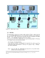
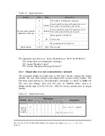
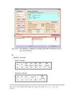
4.6.2 Output data area and communication command
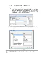
The maximum length of output data is 240 bytes. Before arrange the output
module, the user must arrange and configure the system setting module. The
first three bytes belong to communication commands, as shown in
Table 16
.
The user can change data and I/O state of Modbus Slave device or
DI/DO/AI/AO data of GW-7553-B / GW-7553-M by modify data of output
module.
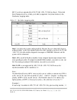
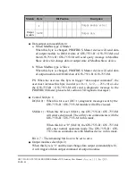
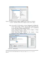
Table 16 Output data area
Module Byte
Bit Position
Description
7
6
5
4
3
2
1
0
System
setting
module
0
Data output command
1
- - - - - - SM DC Control bit
Содержание GW-7553-B
Страница 120: ...GW 7553 B GW 7553 M PROFIBUS Modbus TCP Gateway User Manual Version 1 35 May 2017 PAGE 120 8 Dimensions GW 7553 B...
Страница 121: ...GW 7553 B GW 7553 M PROFIBUS Modbus TCP Gateway User Manual Version 1 35 May 2017 PAGE 121...
Страница 122: ...GW 7553 B GW 7553 M PROFIBUS Modbus TCP Gateway User Manual Version 1 35 May 2017 PAGE 122 GW 7553 M...


