background image

MONOLITE


18 


6 STARTING 

 
IMPORTANT:   before starting insert the flue gas baffles completely in the flue gas pipes, pushing 
them in by at least 100 mm.


6.1 PRELIMINARY 

CHECKS 

Before starting the boiler, make sure that: 

The number plate data corresponds to the electrical, water and liquid or gas fuel supply data; 

The burner rating is compatible with that of the boiler; 

The burner and boiler instructions are available in the boiler room; 

The chimney operates correctly; 

The ventilation openings are adequately dimensioned and free of all obstacles; 

The door, the combustion chamber and the burner plate are closed so that the boiler is gas tight at all 
positions; 

The system has been filled with water and that any air locks have been eliminated; 

There is frost protection; 

The water circulation pumps operate correctly; 

The expansion tank and the safety valve(s) are correctly connected (with no valves) and operative. 


Check the electrical system and that the thermostats are operative. 

6.2 WATER 

TREATMENT 

 
If the boiler is to be installed in an existing system where there could be frequent losses from the 
system or if the hardness of the water is greater than 10 F, it will be necessary to use a filter and a 
softener for system water and control the pH above 8-9. 

The most common phenomena in heating systems are: 

Furring (calcareous deposits of Calcium Carbonate) 

Furring impedes heat exchange between the flue gases and the water, thereby increasing the tempera-
ture of parts exposed to the flame and reducing considerably the boiler life. Furring concentrates where 
the boiler wall temperature is higher, and the best defence against this phenomenon is a boiler design 
that eliminates high temperature spots. 
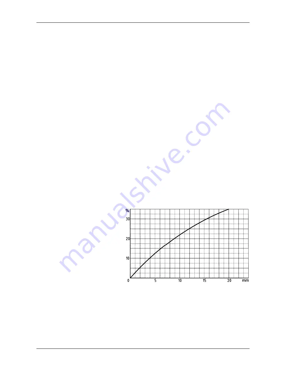
Furring represents an insulation layer that decreases heat exchange, penalising boiler efficiency. This 
means that a large part of the combustion heat is not transferred to the water, but leaves the system via 
the chimney. 
 

Calcium Carbonate Diagram


Legend 
%


% unused fuel 

mm 

mm furring 


Water-side corrosion  

Corrosion of metallic boiler surfaces, 
waterside, is due to Iron dissolving to 
form ions (Fe+). In this process, the 
presence of any dissolved gas plays a 
major role, in particular oxygen and 
carbon dioxide. Often there are corro-
sion phenomena with softened and 
demineralised water, which are by their nature aggressive to iron (acid water, that is  with pH < 7): in 
these cases though clearly there will be no furring, corrosion remains a risk and it will be necessary to 
condition the feedwater with corrosion inhibitors. 

6.3 

FILLING THE SYSTEM 

The water must enter the system as slowly as possible, and in proportion to the rate of air purge from the 
components involved. In the case of a system with a closed expansion tank, water is injected until the pres-
sure gauge reaches the static pressure for the tank. Then proceed to heat the water to the maximum allowed 
plant temperature, but not higher than 90°C. During this operation, the air in the system purges from the 
automatic or manual air separators fitted to the system. On completion of the air purge, bring the pressure to 
the set value and close the manual and/or automatic water supply valve. 

Содержание MONOLITE JB Series

Страница 1: ...TECHNICAL MANUAL MONOLITE GT CONDENSING BOILER WITH PREMIX BURNER MONOLITE JB CONDENSING BOILER WITHOUT BURNER LOW NOx STEEL CONDENSING BOILERS...

Страница 2: ......

Страница 3: ...RE MOD 45 GT 125 GT 13 4 8 INVERTING THE DOOR APERTURE mod 160 GT JB 350 GT 670 JB 13 4 9 PRESSURISED BOILER CONNECTION 14 4 10 WIRING DIAGRAM 14 5 FITTING THE BOILER CASING 15 5 1 BOILER BODY INSULAT...

Страница 4: ...without inversion limits as much as possible the formation of Nitrogen Oxides NOx that form when the flame remains at high temperature in the combustion chamber for long periods The MONOLITE series b...

Страница 5: ...itioned on the control panel should be checked for efficiency The guarantee shall be valid only upon compliance with the instruction given in this manual Our boilers have been built and tested in obse...

Страница 6: ...5 3 89 3 85 78 18 MONOLITE 160 GT 61 53 000 68 58 650 62 53 807 98 5 109 6 62 4 91 4 86 98 65 MONOLITE 210 GT 81 70 000 90 77 462 82 71 066 98 5 109 8 74 6 49 6 42 130 29 MONOLITE 270 GT 104 90 000 11...

Страница 7: ...N10 mm mm mm mm mm mm mm mm mm mm mm DN in DN in DN in DN in DN in DN inDN inDN in DN in DN in MONOLITE 45 GT 1267 1210 670 595 350 322 715 150 150 50 50 1 1 1 2 3 4 1 2 50 3 4 MONOLITE 70 GT 1267 12...

Страница 8: ...4 91 4 86 98 65 MONOLITE 210 JB 81 70 000 90 77 462 82 71 066 98 5 109 0 8 74 6 49 6 42 130 29 MONOLITE 270 JB 104 90 000 116 99 594 106 91 371 98 5 109 0 11 24 8 34 8 25 167 52 MONOLITE 350 JB 136 1...

Страница 9: ...0 JB KEY N1 Boiler flow N2 Medium temperature return N3 Fitting for Instruments N4 System filling drainage N5 Safety valve s fitting N6 Bulbs wells N7 Boiler condensation drain N8 Inspection well N9 L...

Страница 10: ...P8 b c N1 N2 N3 N4 N5 N6 N7 N8 N9 mm mm mm mm mm mm mm mm mm mm mm DN in DN in DN in DN in DN in DN inDN inDN in DN in MONOLITE 30 JB 990 881 670 318 350 322 200 250 150 150 50 50 1 1 1 2 3 4 1 2 50 M...

Страница 11: ...as temperatures produced by MONOLITE boilers are considerably lower than in the case of non condensing boilers and have therefore very high relative humidity For these reasons the chim ney must be com...

Страница 12: ...MONOLITE 10 4 3 1 SEALED HOT WATER HEATING SYSTEM WITH EXPANSION VESSEL Mod 45 125 Mod 160 270...

Страница 13: ...ulation thermostat n 1 19 Regulation thermostat n 2 20 Manual reset safety thermostat 21 Shock absorbing pipe 22 Safety valve n 1 the 2 nd has a heating capacity above 580 kW 23 Fuel shut off valve 24...

Страница 14: ...l thermostats TR1 TR2 have an operating range from 0 to 90 and can be set by the user by means of the front dial Safety limit thermostats TS has a fixed setting of 100 0 6 C and can be manually reset...

Страница 15: ...NVERTING THE DOOR APERTURE mod 160 GT JB 350 GT 670 JB If the door is to be opened to the opposite side act as follows 1 Switch the outside nut or bush of one hinge with the diametrically opposite clo...

Страница 16: ...nd regulations g check that all gas connections are perfectly gas tight h check that the boiler room ventilation openings are dimensioned to guarantee an air flow as foreseen by applicable regulations...

Страница 17: ...r control panel connection cables passing through the aperture for the wiring harness please refer to the control panel diagram and to the standard plugs connection kit Unwind the thermostat capillari...

Страница 18: ...harness please refer to the control panel diagram and to the standard plugs connection kit Unwind the thermostat capillaries fit the control panel to the side fastening with the screw then insert the...

Страница 19: ...e existing opening for the wiring harness please refer to the control panel diagram and to the standard plugs connection kit Unwind the thermostat capillaries attach the control panel 3 to the side wi...

Страница 20: ...osed to the flame and reducing considerably the boiler life Furring concentrates where the boiler wall temperature is higher and the best defence against this phenomenon is a boiler design that elimin...

Страница 21: ...er WARNING during long stoppages in winter and in order to avoid frost damage drain both the sanitary wa ter and the heating system water drainage of the latter can be avoided by adding antifreeze Boi...

Страница 22: ...arted in via G Pascoli 38 37059 Campagnola di Zevio VR Italia DECLARE THAT BOILERS MONOLITE 45 GT 70 GT 95 GT 125 GT with burner MONOLITE 160 GT 210 GT 270 GT 350 GT body only MONOLITE JB comply with...

Страница 23: ......

Страница 24: ...scoli 38 Zevio fraz Campagnola VERONA ITALIA Tel 045 8738511 Fax 045 8731148 info icicaldaie com www icicaldaie com The data reported are indicative only and are not binding Our company reserves the r...

Отзывы: