ELEVATION SERIES CIM CUBER
HARVEST ASSIST ASSEMBLY/HOT GAS VALVE
48
Harvest Assist Assembly/Hot Gas Valve
Operation
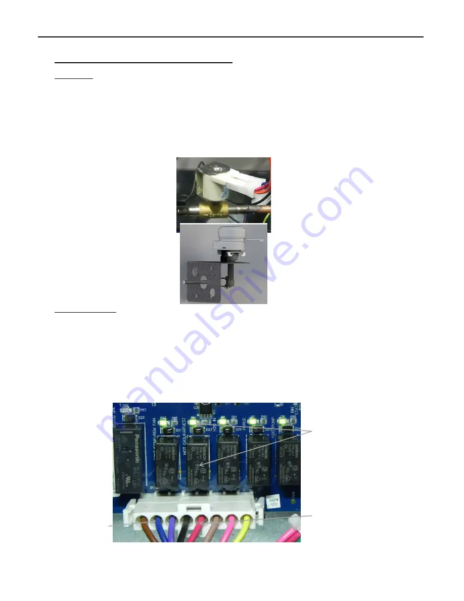
The Harvest Assist Assembly is mounted to the back of the Evaporator Assembly. It is energized
by Relay 3 along with the Hot Gas Valve. As the unit enters the Harvest Cycle, Relay 3 will illumi‐
nate indicating voltage is being sent to the Harvest Assist Assembly and the probe will be pushed
forward to meet the ice slab.As the Evaporator warms, the Probe on the Harvest Assist will move
forward to help release the ice from the plate. As the ice slab falls it will open the Magnetic Cur‐
tain Switch contacts. Relay 3 will then be de‐energized and the Harvest Assist will automatically
return to the starting position.
Troubleshooting
The Harvest Assist Assembly is energized with the Hot Gas Valve throughout the Defrost Cycle by
Relay 3. To quickly verify operation, put the unit into Diagnostics program by pressing both the
Power and Wash buttons for 6 seconds, then quick press BOTH the Power and Clean buttons
until the Harvest Cycle is initiated (R2 ‐ R6 LED’s above component Molex should illuminate).
Verify LED for Relay 3 is illuminated and check voltage between the Blue and Red wires at Molex.
If no voltage is present, the Board or Molex may be the issue. If voltage is verified, Check for
voltage at the wiring connector for the Harvest Assist. If voltage is verified and the probe is not
pushed forward, the issue is the Harvest Assist.
R3 Hot Gas/Harvest
Assist LED
L2/N
Hot Gas/Harvest
Assist
Содержание CIM Series
Страница 31: ...ELEVATION SERIES CIM CUBERS BOARD COMPONENT LED SEQUENCE 29 INITIAL HARVEST CYCLE AT START UP ...
Страница 32: ...ELEVATION SERIES CIM CUBERS BOARD COMPONENT LED SEQUENCE 30 TRANSITION FROM HARVEST TO FREEZE ...
Страница 33: ...ELEVATION SERIES CIM CUBERS BOARD COMPONENT LED SEQUENCE 31 BIN FULL CURTAIN OR STAT ...
Страница 35: ...ELEVATION SERIES CIM CUBERS BOARD COMPONENT LED SEQUENCE 33 DIAGNOSTICS IN HARVEST CYCLE ...
Страница 36: ...ELEVATION SERIES CIM CUBERS BUTTON FUNCTIONS 34 Button Functions ...
Страница 77: ...ELEVATION SERIES WIRING DIAGRAM 75 CIM220V 240V 50Hz SINGLE PHASE SINGLE EVAPORATOR REMOTE COOLED UINTS ...
Страница 78: ...ELEVATION SERIES WIRING DIAGRAM 76 CIM 230V 60Hz THREE PHASE SINGLE EVPAORATOR PLATE REMOTE COOLED UNITS ...
Страница 80: ...ELEVATION SERIES WIRING DIAGRAM 78 CIM 220V 240V 50Hz SINGLE PHASE DUAL EVAPORATOR AIR AND WATER COOLED UNITS ...
Страница 81: ...ELEVATION SERIES WIRING DIAGRAM 79 CIM 230V 60Hz THREE PHASE DUAL EVAPORATOR AIR AND WATER COOLED UNITS ...
Страница 82: ...ELEVATION SERIES WIRING DIAGRAM 80 CIM 115V and 230V 60Hz SINGLE PHASE DUAL EVAPORATOR REMOTE COOLED UNITS ...
Страница 83: ...ELEVATION SERIES WIRING DIAGRAM 81 CIM 220V 240V 50Hz SINGLE PHASE DUAL EVAPORATOR REMOTE COOLED UNITS ...
Страница 84: ...ELEVATION SERIES WIRING DIAGRAM 82 CIM 230V 60Hz THREE PHASE DUAL EVAPORATOR REMOTE COOLED UNITS ...


