5 of 7
Removing the Controller from the Computer
Follow these steps to remove the controller from the
computer.
1.
Turn off the power, and unplug the power cords.
2.
Ground yourself and make sure the system is
grounded.
3.
Remove the cover from the computer, according to the
instructions in the system user’s manual, to allow
access to the controller.
4.
Unplug all cables from the controller, remove the screw
attaching the bracket to the computer chassis, and
carefully remove the controller from the slot.
5.
Place the controller on a flat, clean, static-free surface,
and continue with the next procedure.
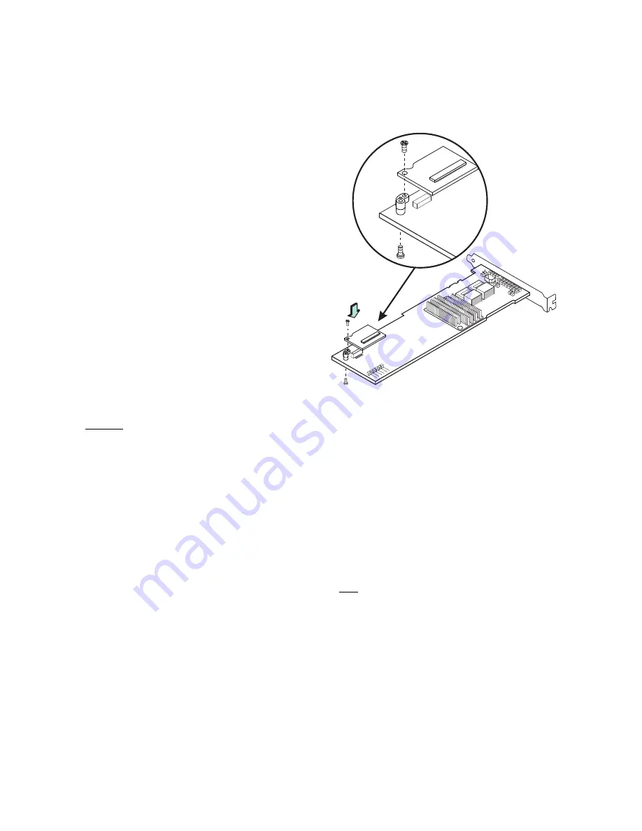
Installing the Interposer Card on the Controller
Follow these steps to install the interposer card on the
controller, as shown in the following figure.
1.
With the controller on a flat, clean, static-free surface,
ground yourself and make sure the system is grounded.
2.
Remove the interposer card, standoff, and screws from
the package.
3.
Place the standoff on the controller so that the bottom
side is over the screwhole next to the JT3 BBU
connector on the controller.
4.
Use one of the screws to secure the standoff to the
controller.
Important:
Center the screwdriver carefully to avoid stripping
the screwhead. Do not overtighten the screws.
5.
Hold the interposer card so that the J1 board-to-board
connector on the interposer card lines up with the JT3
board-to-board connector on the controller.
6.
Carefully press the J1 connector on the interposer card
into the JT3 connector on the controller so that the two
connectors are firmly joined.
The connectors fit only when they are in the correct
alignment.
7.
Use the other screw to secure the interposer card to the
controller and continue with the next procedure.
Figure 6 Connecting the Interposer Card to the
Controller
Connecting the Cable Between the Interposer Card and
the Controller
Follow these steps to connect the cable between the
interposer card on the controller and the ServeRAID M5000
Series Battery Kit.
1.
Mount the battery kit to the chassis of your computer
based on the location and the type of mounting option.
2.
With the controller on a flat, clean, static-free surface,
ground yourself and make sure the system is grounded.
3.
Remove the cable included in the battery kit.
4.
Insert one end of the cable into the 20-pin J2 connector
on the battery kit and the other end into the 20-pin J1
connector on the interposer card, as shown in the
following figure.
Align the recessed triangle indicators on the connectors
to make sure they are connected properly.
Note:
The cable connectors are polarized and can be
inserted into the connectors on the interposer
card and the battery kit only if the rails on the
cable connectors align with the slots on the other
connectors.
Do not
force the cable into the 20-
pin connectors. The cable end inserts into the
connector with minimal resistance.
85039-07


