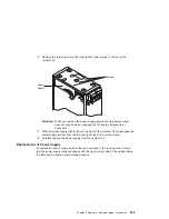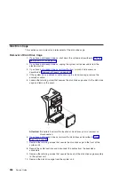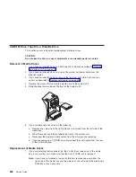
7. Disconnect the six power cables from the power supply connectors in the following
order (P3, P4, P6, P5, P2, and P1). Ensure that the cables allow clearance for
power supply removal.
8. Remove the power cables from the I/O board connectors (J16 and J19).
9. Remove the retaining screws that secure the power supply to the rear of the
system unit.
P1
P2
P3
P4
P5
P6
Front View
Side View
Power Supply
Power
Supply
Screws (4)
258
Service Guide
Содержание RS/6000 44P Series 270
Страница 1: ...RS 6000 44P Series Model 270 Service Guide SA38 0572 02 ...
Страница 10: ...x Service Guide ...
Страница 14: ...xiv Service Guide ...
Страница 16: ...xvi Service Guide ...
Страница 20: ...Rear View 1 2 3 4 5 6 7 8 9 11 12 13 14 15 16 10 17 18 19 2 Service Guide ...
Страница 44: ...26 Service Guide ...
Страница 164: ...146 Service Guide ...
Страница 204: ...186 Service Guide ...
Страница 245: ...3 To remove the rear cover lift the cover up and away from the system Chapter 9 Removal and Replacement Procedures 227 ...
Страница 247: ...b Slide the covers to the rear and remove Chapter 9 Removal and Replacement Procedures 229 ...
Страница 288: ...270 Service Guide ...
Страница 289: ...Chapter 10 Parts Information This chapter contains parts information for the RS 6000 44P Series Model 270 271 ...
Страница 290: ...1 2 3 4 5 6 7 8 9 10 11 12 13 14 15 16 17 18 19 21 20 22 23 24 25 272 Service Guide ...
Страница 294: ...Keyboards and Mouse 276 Service Guide ...
Страница 296: ...Keyboards and Mouse Black 278 Service Guide ...
Страница 298: ...Power Cables 1 2 3 4 5 6 7 8 9 10 11 280 Service Guide ...
Страница 300: ...282 Service Guide ...
Страница 302: ...284 Service Guide ...
Страница 304: ...286 Service Guide ...
Страница 310: ...292 Service Guide ...
Страница 338: ...320 Service Guide ...
Страница 345: ......
Страница 346: ... Printed in U S A September 2001 SA38 0572 02 ...

