Tip:
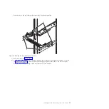
Save the shipping cover and screws that you have removed for any future shipping of the
expansion unit that might be required.
b.
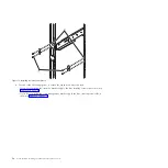
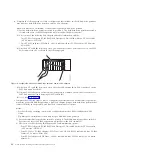
If the bezel is installed on the front of the system, remove it by completing the following steps:
1)
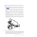
Remove the two M5 securing screws
(A)
as shown in Figure 7.
2)
Remove the service information holder from the slot in the bezel.
3)
Using the two blue touch points on each side of the expansion unit, pull the bezel straight out
to remove the bezel from the front of the expansion unit.
4)
Remove the two nut clips that were used to secure the bezel to the expansion unit from the
Electronic Industries Alliance (EIA) flange.
c.
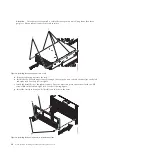
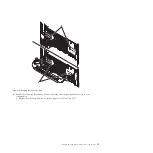
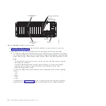
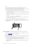
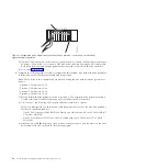
Using three people, hold onto the four handles
(I)
, as shown in the following figure, to lift the
expansion unit and position it over the front of the rails.
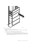
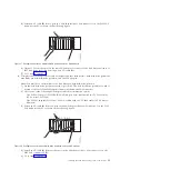
Figure 6. Removing the shipping cover
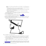
Figure 7. Removing the service information holder and bezel
Installing the 5802 and 5877 expansion units: Details
9
Содержание Power System 5802
Страница 1: ...Power Systems Installing the 5802 and 5877 expansion units GI11 4307 09...
Страница 2: ......
Страница 3: ...Power Systems Installing the 5802 and 5877 expansion units GI11 4307 09...
Страница 6: ...iv Power Systems Installing the 5802 and 5877 expansion units...
Страница 38: ...26 Power Systems Installing the 5802 and 5877 expansion units...
Страница 52: ...40 Power Systems Installing the 5802 and 5877 expansion units...
Страница 62: ...50 Power Systems Installing the 5802 and 5877 expansion units...
Страница 63: ......
Страница 64: ...Part Number 00L5079 Printed in USA GI11 4307 09 1P P N 00L5079...


