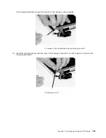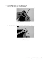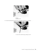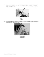
14.
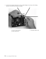
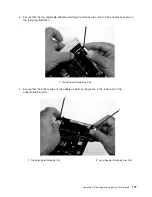
Check
for
the
following:
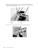
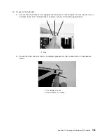
a.
Ensure
that
the
extension
arm
engages
the
three
pins
on
the
cassette.
You
can
see
the
pins
in
the
holes
in
the
arm.
The
bezel
tab
is
seated
as
shown
in
the
following
illustration.
1
1
1
1
Pins
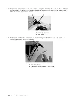
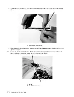
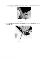
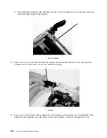
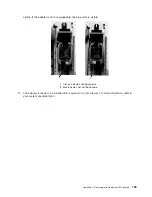
b.
Ensure
that
the
cover
arm
latch
is
completely
pressed
into
the
hooked
notch
on
the
bezel
as
shown.
1
2
1
PCI
Adapter
Pull
Tab
2
Hooked
Notch
in
the
Bezel
Appendix
C.
Removing
and
Replacing
PCI
Adapters
183
Содержание p 655 series
Страница 1: ...pSeries 655 User s Guide SA38 0617 03 ERserver...
Страница 2: ......
Страница 3: ...pSeries 655 User s Guide SA38 0617 03 ERserver...
Страница 10: ...viii Eserver pSeries 655 User s Guide...
Страница 14: ...xii Eserver pSeries 655 User s Guide...
Страница 16: ...xiv Eserver pSeries 655 User s Guide...
Страница 24: ...6 Eserver pSeries 655 User s Guide...
Страница 32: ...14 Eserver pSeries 655 User s Guide...
Страница 36: ...18 Eserver pSeries 655 User s Guide...
Страница 90: ...72 Eserver pSeries 655 User s Guide...
Страница 144: ...126 Eserver pSeries 655 User s Guide...
Страница 208: ...190 Eserver pSeries 655 User s Guide...
Страница 214: ...196 Eserver pSeries 655 User s Guide...
Страница 217: ......
Страница 218: ...Printed in USA February 2004 SA38 0617 03...

