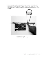
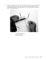
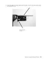

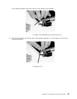
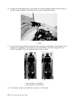
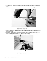
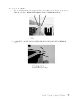
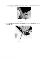

The
following
illustration
shows
the
location
of
the
bushing
in
the
cassette.
1
1
Location
of
the
Installed
Bushing
and
Bushing-Lock
Pin
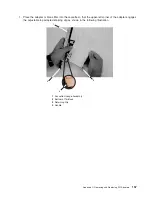
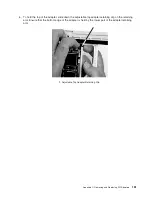
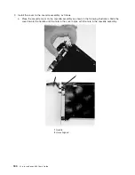
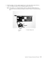
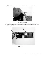
13.
Insert
the
bushing-lock
pin
into
the
hole
in
the
bushing,
and
push
it
in
until
it
seats
as
shown
in
the
following
illustration.
1
1
Bushing-Lock
Pin
Appendix
C.
Removing
and
Replacing
PCI
Adapters
169
Содержание p 655 series
Страница 1: ...pSeries 655 User s Guide SA38 0617 03 ERserver...
Страница 2: ......
Страница 3: ...pSeries 655 User s Guide SA38 0617 03 ERserver...
Страница 10: ...viii Eserver pSeries 655 User s Guide...
Страница 14: ...xii Eserver pSeries 655 User s Guide...
Страница 16: ...xiv Eserver pSeries 655 User s Guide...
Страница 24: ...6 Eserver pSeries 655 User s Guide...
Страница 32: ...14 Eserver pSeries 655 User s Guide...
Страница 36: ...18 Eserver pSeries 655 User s Guide...
Страница 90: ...72 Eserver pSeries 655 User s Guide...
Страница 144: ...126 Eserver pSeries 655 User s Guide...
Страница 208: ...190 Eserver pSeries 655 User s Guide...
Страница 214: ...196 Eserver pSeries 655 User s Guide...
Страница 217: ......
Страница 218: ...Printed in USA February 2004 SA38 0617 03...


