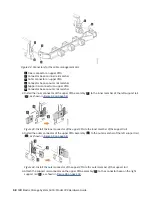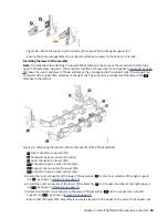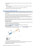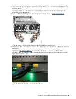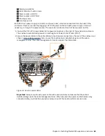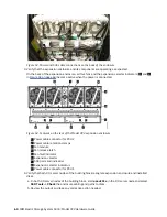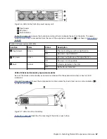
Figure 53. Power and SAS cable connections on the back of the enclosure
3. Verify that the expansion enclosure and its components are operating as expected.
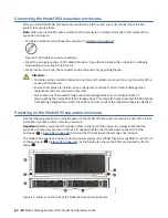
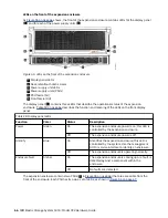
On the back of the expansion enclosure, all four fans and the expansion canister indicators (
3
and
8
in Figure 54 on page 64) become active when the power is connected.
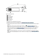
Figure 54. Features on the rear of the Model 092 expansion enclosure
1
Power cable connector for PSU 2
2
Power cable retention clamps
3
Fan module
4
Fan release latch
5
Fan fault indicator
6
Expansion canister
7
SAS ports and indicators
8
Expansion canister indicators
9
Power cable connector for PSU 1
4. Verify that both I/O server nodes of the building block recognize expansion enclosure and installed
disks.
a. In both I/O server nodes of the building block, start
essutils
in the I/O server node and select
SSR Tools -> Check the enclosure cabling and paths to disks.
b. Review the output and take any corrective action needed.
64 IBM Elastic Storage System 5000: Model 092 Hardware Guide
Содержание Elastic Storage System 5000 Series
Страница 1: ...IBM Elastic Storage System 5000 Version 6 0 1 Model 092 Hardware Guide IBM SC28 3135 00...
Страница 8: ...viii...
Страница 10: ...24 Enclosure models and rack requirements 74 x...
Страница 14: ...xiv IBM Elastic Storage System 5000 Model 092 Hardware Guide...
Страница 32: ...18 IBM Elastic Storage System 5000 Model 092 Hardware Guide...
Страница 36: ...22 IBM Elastic Storage System 5000 Model 092 Hardware Guide...
Страница 51: ...Figure 11 Cable connectivity from I O servers Chapter 4 Planning for hardware 37...
Страница 86: ...72 IBM Elastic Storage System 5000 Model 092 Hardware Guide...
Страница 90: ...76 IBM Elastic Storage System 5000 Model 092 Hardware Guide...
Страница 98: ...84 IBM Elastic Storage System 5000 Model 092 Hardware Guide...
Страница 100: ...86 IBM Elastic Storage System 5000 Model 092 Hardware Guide...
Страница 101: ......
Страница 102: ...IBM Product Number 5765 DME 5765 DAE SC28 3135 00...

