


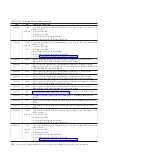


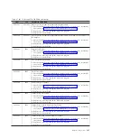


Table 27. 101-711 through FFC-725 SRNs (continued)
SRN
FFC
Description and Action
2E14-701
2E14 221
Error Log Analysis indicates permanent adapter failure.
1.
Check the BladeCenter management-module event log. If an error was recorded by
the system, see “POST progress codes (checkpoints)” on page 97.
2.
Replace any parts reported by the diagnostic program.
3.
Replace the system-board
2E14-702
2E14 221
Error Log Analysis indicates permanent adapter failure is reported
1.
Check the BladeCenter management-module event log. If an error was recorded by
the system, see “POST progress codes (checkpoints)” on page 97.
2.
Replace any parts reported by the diagnostic program.
3.
Replace the system-board
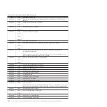
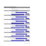
2E15-201
2E15 221
Adapter configuration error.
1.
Check the BladeCenter management-module event log. If an error was recorded by
the system, see “POST progress codes (checkpoints)” on page 97.
2.
Replace any parts reported by the diagnostic program.
3.
Replace the system-board
2E15-601
2E15
Error Log Analysis indicates adapter failure.
1.
Check the BladeCenter management-module event log. If an error was recorded by
the system, see “POST progress codes (checkpoints)” on page 97.
2.
Replace any parts reported by the diagnostic program.
3.
Replace the system-board
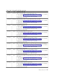
2E15-602
2E15
Error Log Analysis indicates an Error Attention condition.
1.
Check the BladeCenter management-module event log. If an error was recorded by
the system, see “POST progress codes (checkpoints)” on page 97.
2.
Replace any parts reported by the diagnostic program.
3.
Replace the system-board
2E15-603
2E15
Error Log Analysis indicates that the microcode could not be loaded on the adapter.
1.
Check the BladeCenter management-module event log. If an error was recorded by
the system, see “POST progress codes (checkpoints)” on page 97.
2.
Replace any parts reported by the diagnostic program.
3.
Replace the system-board
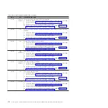
2E15-604
2E15
Error Log Analysis indicates a permanent adapter failure.
1.
Check the BladeCenter management-module event log. If an error was recorded by
the system, see “POST progress codes (checkpoints)” on page 97.
2.
Replace any parts reported by the diagnostic program.
3.
Replace the system-board
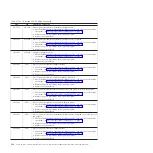
2E15-605
2E15
Error Log Analysis indicates permanent adapter failure is reported on the other port of
this adapter.
1.
Check the BladeCenter management-module event log. If an error was recorded by
the system, see “POST progress codes (checkpoints)” on page 97.
2.
Replace any parts reported by the diagnostic program.
3.
Replace the system-board
2E15-606
2E15
Error Log Analysis indicates adapter failure.
1.
Check the BladeCenter management-module event log. If an error was recorded by
the system, see “POST progress codes (checkpoints)” on page 97.
2.
Replace any parts reported by the diagnostic program.
3.
Replace the system-board
Chapter 2. Diagnostics
163
Содержание BladeCenter PS703
Страница 2: ......
Страница 26: ...14 Power Systems Problem Determination and Service Guide for the IBM PS703 7891 73X and PS704 7891 74X...
Страница 240: ...228 Power Systems Problem Determination and Service Guide for the IBM PS703 7891 73X and PS704 7891 74X...
Страница 278: ...266 Power Systems Problem Determination and Service Guide for the IBM PS703 7891 73X and PS704 7891 74X...
Страница 286: ...274 Power Systems Problem Determination and Service Guide for the IBM PS703 7891 73X and PS704 7891 74X...
Страница 297: ......
Страница 298: ...Printed in USA GI11 9841 00...