Notes:
1.
Copper pass-thru module cable connectors are marked as A, B, C, D, and E
to indicate their channel number.
2.
The port-3 E connector is not used.
Information LEDs
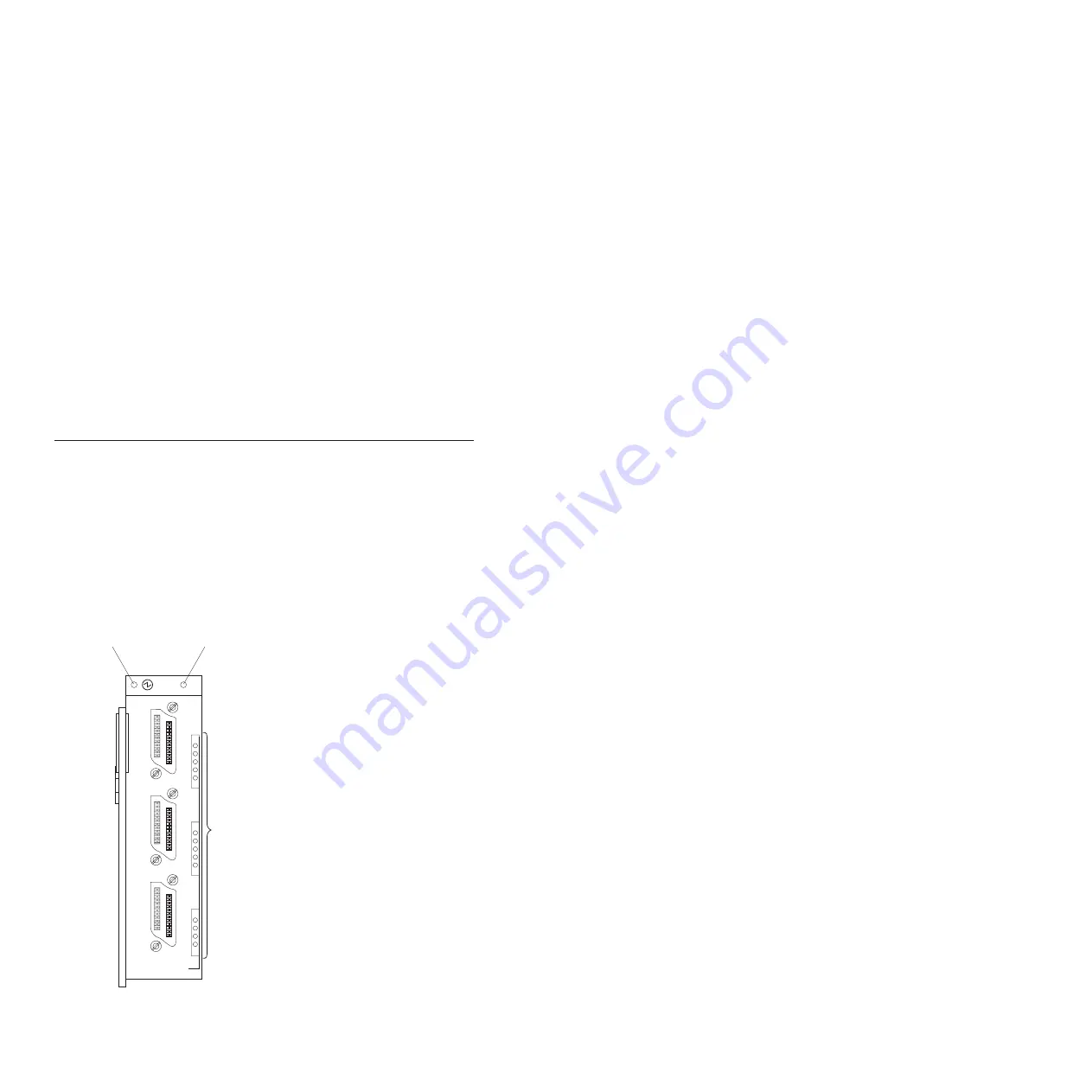
There are two sets of LEDs on the copper pass-thru module front panel. The
first row of LEDs at the top of the I/O module represent I/O-module status
and include the power LED and the copper pass-thru module error LED (!).
The second set of LEDs are grouped in an LED matrix that indicates the link
status for each copper-port channel and copper-port errors. The following
illustration shows the LEDs on the copper pass-thru module. A description of
each LED follows the illustration.
1
5
6
10
11
14
1
2
3
LINK OK
!
Copper Pass-thru
Module error LED
Power LED
Link OK LEDs
Figure 6. Information LEDs
Chapter 3. Information LEDs and external ports
25
Содержание BladeCenter Copper Pass-thru
Страница 1: ...IBM BladeCenter Copper Pass thru Module Installation Guide...
Страница 2: ......
Страница 3: ...IBM BladeCenter Copper Pass thru Module Installation Guide...
Страница 14: ...xii IBM BladeCenter Copper Pass thru Module Installation Guide...
Страница 36: ...22 IBM BladeCenter Copper Pass thru Module Installation Guide...
Страница 55: ......
Страница 56: ...Part Number 25R4622 02 Printed in USA...


