background image

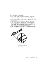
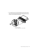
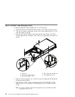
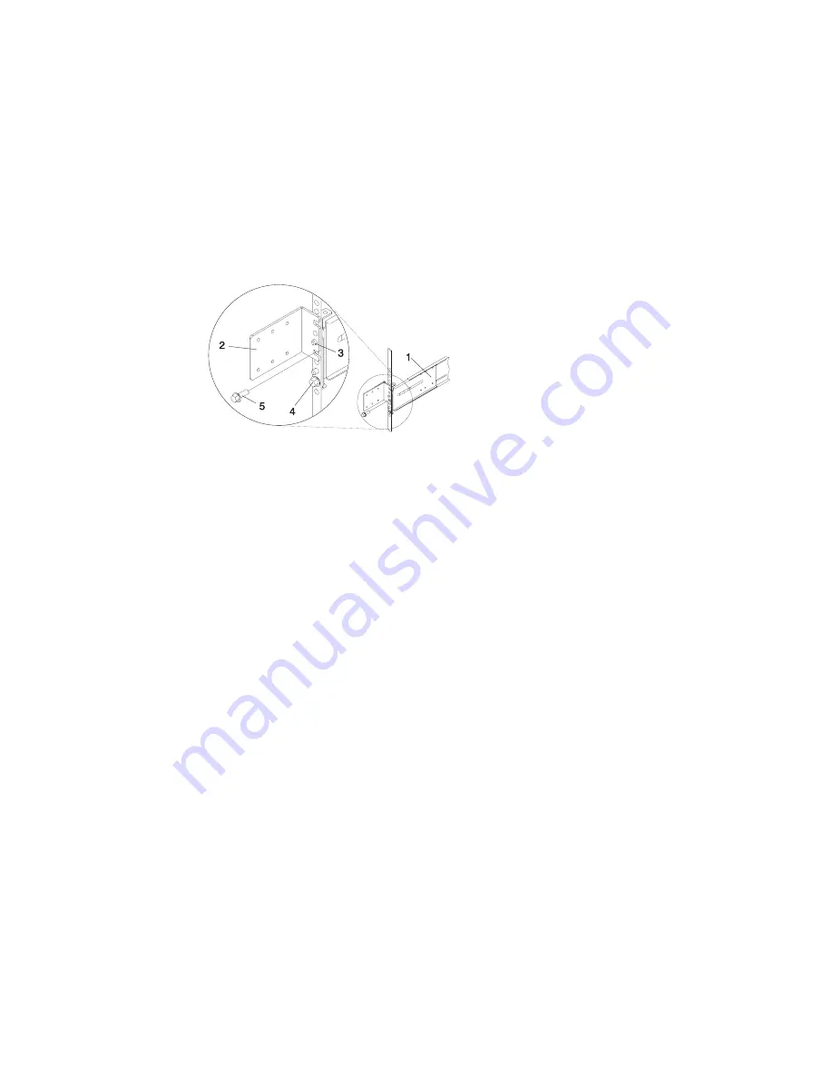
Rail Assembly (Labeled

Left

in the Front Lower Corner)

Rack to Cable Management Arm Bracket

Top Rear Alignment Pin

Bottom Screw

Top Screw

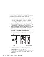
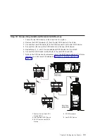
18. Locate the bracket that attaches the cable management arm to the rack flange.

19. Position the bracket’s bottom hole over the rail’s top alignment pin.

Note: The bracket’s bottom slot should now align with the top screw hole of the

rail flange.

20. Attach a second retaining screw through the screw hole located below the top

alignment pin. Finger-tighten the screw.

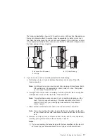
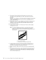
21. Using a screwdriver, tighten the six screws that secure the rail length adjusting

plate.

22. The rails are now completely installed. All screws used to attach the rails to the

rack must be finger-tight only.

Notes:

a. Both slide rails

must be completely retracted into the rack.

b. The rails

must be level from front to back and from left to right.

23. Before continuing to the next step, be sure to read and understand the following

caution notices:

CAUTION:
The stabilizer must be firmly attached to the bottom front of the rack to
prevent the rack from turning over when the drawers are pulled out of the
rack. Do not pull out or install any drawer or feature if the stabilizer is not
attached to the rack.

CAUTION:
This unit weighs between 32 kg (70.5 pounds) and 55 kg (121.2 pounds).
Three persons are required to safely move it. Using fewer than three persons
to move it can result in injury.

You are now ready to mount the system drawer into the rack.

Chapter 2. Setting Up the System

21

Содержание @Server pSeries 630 6C4

Страница 1: ...pSeries 630 Model 6C4 and Model 6E4 Installation Guide SA38 0605 01 ERserver IBM...

Страница 2: ......

Страница 3: ...pSeries 630 Model 6C4 and Model 6E4 Installation Guide SA38 0605 01 ERserver IBM...

Страница 4: ...nts to Information Development Department H6DS 905 6C006 11501 Burnet Road Austin Texas 78758 3493 To send comments electronically use this commercial internet address aix6kpub austin ibm com Any info...

Страница 5: ...Read the Safety Notices 10 Step 4 Are You Installing a Model 6C4 Rack Mount or a Model 6E4 Deskside 11 Step 5 Read the Rack Safety Instructions 12 Rack Safety Instructions 12 Step 6 Attach the Mountin...

Страница 6: ...rvice Mode 46 Step 2 Running the Verification Procedure 47 Step 3 Performing Additional System Verification 47 Step 4 Stopping the Diagnostics 47 Chapter 4 Installing Options for the Model 6C4 and Mod...

Страница 7: ...in a Non Hot Swap Environment 94 Hot Swap Fan Assembly Removal 95 Hot Swap Fan Assembly Replacement 98 Media Drives Diskette CD ROM Tape or Disk Drive 100 Media Drive Removal 100 Media Drive Replaceme...

Страница 8: ...and Attention LEDs 141 Operator Panel Display 141 Component LEDs 142 Reporting the Problem 143 Repair Action 144 Resetting the LEDs 144 Appendix E System Records 145 Identification Numbers 145 Device...

Страница 9: ...w through the unit must not be in direct contact with the rack v Care should be taken to ensure that a hazardous condition is not created due to uneven mechanical loading when installing this unit in...

Страница 10: ...ving signal cables ensure that the power cables for the system unit and all attached devices are unplugged When adding or removing any additional devices to or from the system ensure that the power ca...

Страница 11: ...ion numbers and approval information CAUTION All IBM laser modules are designed so that there is never any human access to laser radiation above a class 1 level during normal operation user maintenanc...

Страница 12: ...x Eserver pSeries 630 Model 6C4 and Model 6E4 Installation Guide...

Страница 13: ...ges or component failures must verify the accuracy of operations performed and data saved or transmitted by the system at or near the time of the outage or failure In addition users must establish pro...

Страница 14: ...xii Eserver pSeries 630 Model 6C4 and Model 6E4 Installation Guide...

Страница 15: ...pSeries Diagnostic Information for Multiple Bus Systems order number SA38 0509 contains diagnostic information service request numbers SRNs and failing function codes FFCs v The RS 6000 Eserver pSeri...

Страница 16: ...hy Computing Web site gives ergonomic guidelines to help you understand the ergonomic considerations that you should know when working at a computer workstation The address is http www us pc ibm com h...

Страница 17: ...6C4 and Model 6E4 environment The following information is included in the chapter v Eserver pSeries Roadmap v Documentation Overview Brief description of the printed and softcopy documentation shippe...

Страница 18: ...dmap helps you locate marketing service and customer task information The roadmap guides you through the tasks and the publications that document those tasks 2 Eserver pSeries 630 Model 6C4 and Model...

Страница 19: ...rmation on how to install system hardware cable the system and verify operations Service personnel printed and softcopy IBM Hardware Management Console for pSeries Operations Guide Provides informatio...

Страница 20: ...PCI Adapter Placement Reference Outlines system specific PCI adapter slot placement and adapter support configurations Service personnel printed Hardware Management Console for pSeries Maintenance Gui...

Страница 21: ...e smitty install_latest 2 Enter INPUT device directory for software in the field provided and press Enter 3 In the Install Software menu use the F4 key to list the documentation packages and filesets...

Страница 22: ...6 Eserver pSeries 630 Model 6C4 and Model 6E4 Installation Guide...

Страница 23: ...s chapter Step 1 Check Your Inventory pSeries 630 Model 6C4 and Model 6E4 h Books CD ROM and Other Media h About Your Machine Document h Power Cables 1 standard 2 optional h 9 Pin to 25 Pin Serial Con...

Страница 24: ...ge h Display Cable optional and Cable Toroid optional h Keyboard optional Wrist Palm Rest optional h Mouse optional Eserver pSeries 630 Model 6C4 and Model 6E4 hModel 6C4 hModel 6E4 8 Eserver pSeries...

Страница 25: ...Mounting Kit contains 8 system to rail screws 8 rail to rack screws 2 nut clips 2 latch mounting brackets 2 system retaining thumbscrews 4 alignment pin brackets 8 assorted alignment pins 1 strip of s...

Страница 26: ...that is not correctly wired could place hazardous voltage on metal parts of the system or the devices that attach to the system It is the responsibility of the customer to ensure that the outlet is c...

Страница 27: ...shock hazard disconnect all power cables from the electrical outlet before relocating the system Step 4 Are You Installing a Model 6C4 Rack Mount or a Model 6E4 Deskside v If you are installing a Mode...

Страница 28: ...cal loading when installing this unit in a rack If the rack has a stabilizer it must be firmly attached before installing or removed this unit v Consider the connection of the equipment to the supply...

Страница 29: ...read then perform each procedure step in the order given Failure to do so may cause rail failure resulting in system drawer damage or bodily injury To install the rack mounting hardware to the rack do...

Страница 30: ...move the brackets from the rails To remove the alignment pin bracket from each of the rails do the following 1 Remove the screw located on top of the rail bracket assembly 2 Slide the top of the align...

Страница 31: ...he front rack door and if necessary remove the rear rack door For 7014 Model T00 and T42 racks refer to 7014 Model T00 and T42 Rack Installation and Service Guide order number SA38 0577 for informatio...

Страница 32: ...he protective coating from each adhesive strip located on the back of the rack mounting template Lightly press the template into position on the rack Ensure that both the left and right side are at co...

Страница 33: ...tall is 4 EIA b Facing the front of the rack and working from the right side place a supplied self adhesive dot next to the top hole of the bottom EIA Note The self adhesive dots are used to aid in id...

Страница 34: ...s to the rack 3 There is an 8 hole span when counting from the nut clip to the bottom dot e Do the same procedure to corresponding holes located on the left side of the rack 5 Beginning with the right...

Страница 35: ...o back 9 Loosely thread one of the rail retaining screws into the rail s bottom screw hole This is the screw hole located one position below the bottom alignment pin Attention To install the rack rail...

Страница 36: ...il length adjusting plate should not move freely when loosened however you should be able to make an adjustment by moving the adjustment plate with one hand and holding the remaining portion of rail i...

Страница 37: ...All screws used to attach the rails to the rack must be finger tight only Notes a Both slide rails must be completely retracted into the rack b The rails must be level from front to back and from left...

Страница 38: ...completely remove the drawer away from the outer rails After the drawer is clear of the outer rails reposition the system then reinsert the inner rails Do this until the system drawer glides freely in...

Страница 39: ...ck enclosure by inserting transport retaining screws through each side of the bezel and chassis bracket Each screw is held in place with a nut clip positioned over a predetermined rack flange hole 1 M...

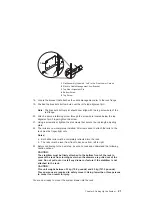
Страница 40: ...the head of the snap buttons locks them into position 1 Model 6C4 4 Rack Flange Mounting Bracket 2 Cable Carrier Support Bracket 5 Cable Management Arm 3 Captive Snap Button Qty 2 4 Open the cable man...

Страница 41: ...terminals can weigh as much as 35 kg 77 pounds Use caution when lifting or moving the display or ASCII terminal v Leave enough space around the system unit to safely and easily complete the setup proc...

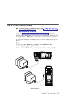
Страница 42: ...the graphics adapter has been set to use the highest display resolution and refresh rate available for that display If you want to v Attach another display to your system unit OR v Change the default...

Страница 43: ...ices on page 10 2 This system drawer is equipped with two HMC connectors located on the back of the system The connectors are labeled HMC1 and HMC2 To connect your HMC to the Model 6C4 or Model 6E4 co...

Страница 44: ...cable for your display does not include a toroid locate the toroid shipped with your system and follow the installation instructions included with the toroid 1 Display Cable Toroid 28 Eserver pSeries...

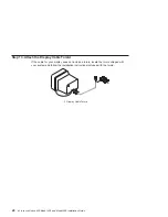
Страница 45: ...display cable to the back of the display and to the graphics adapter connector For the locations of installed adapters consult the About Your Machine document For more information about your display r...

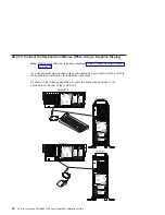
Страница 46: ...ces on page 10 If a wrist palm rest was included with your keyboard and you want to attach it refer to the keyboard documentation for installation instructions As shown in the following illustration c...

Страница 47: ...is deactivated 5 Use a 9 pin to 25 pin serial converter cable when activating the rear serial port 1 The 9 to 25 pin serial converters are a customer purchased option 6 If you have a remote ASCII term...

Страница 48: ...er connect it to the parallel connector 4 1 Serial Port 1 Connector 1a Serial Port 1 Front Connector RJ48 2 Serial Port 2 Connector 3 Serial Port 3 Connector 4 Parallel Connector 32 Eserver pSeries 63...

Страница 49: ...ty Notices on page 10 If you are using any optional adapters such as token ring or 8 port EIA 232 connect the cables to the appropriate adapter connectors in the PCI slots of your machine For the loca...

Страница 50: ...e next step Note The built in SCSI interface is Ultra3 SCSI When a cable is not attached to the SCSI connector on the system the SCSI bus is automatically terminated 4 Refer to the SCSI device documen...

Страница 51: ...3 to the new SCSI device 5 Repeat steps 1 2 and 3 for each additional SCSI device that you attach 6 Connect the SCSI device terminator 4 to the last SCSI device 5 7 Refer to the SCSI device documenta...

Страница 52: ...system administrator if you are unsure whether you are using the rack indicator feature If you are not using the rack indicator feature continue to Step 21 Are You Using an Ethernet Connection on page...

Страница 53: ...m on page 38 To connect the Ethernet cable do the following Note The twisted pair connector is compatible with the IEEE 802 3 Ethernet network 10 100 Base T link 1 Connect the twisted pair cable to on...

Страница 54: ...the power cable to the power receptacle A second power receptacle is available when a second redundant power supply has been added to the system drawer See the following illustration 1 Default Power S...

Страница 55: ...extended position with a click 2 Loosely wrap the Velcro strips around the external cables The Velcro strip was already premounted on your cable management arm Note To allow for cable movement do not...

Страница 56: ...D 7 FS1 Front Serial Connector RJ48 Connector 3 Attention LED 8 CSP Reset Button Pinhole 4 SCSI Port Activity 9 System Reset Button 5 Ethernet Port Activity If your system does not stop in standby mod...

Страница 57: ...the system as follows a Look for OK in the operator panel display which indicates that the system is in standby mode The green power LED should be blinking slowly b Press the power button on the opera...

Страница 58: ...shop publications order Operating System Documentation Documentation for the AIX operating system is available either from the AIX documentation CD or from the Web If you ordered the AIX documentation...

Страница 59: ...unit is directly attached to another system unit or attached to a network be sure communication with the other systems is stopped v This procedure requires use of all of the system resources No other...

Страница 60: ...g figure shows the operator panel and the locations of operator panel components that are referred to in this procedure 1 Power On Button 6 Operator Panel Display 2 Power LED 7 FS1 Front Serial Connec...

Страница 61: ...resource on the Diagnostic Selection menu The checkout programs end with either of the following results v The Testing Complete menu displays with a message stating No trouble was found v The A Probl...

Страница 62: ...control menu 6 Use the HMC to power on the managed system in a full system partition by selecting the managed system in the Contents area 7 Right click or select the desired system in the Contents are...

Страница 63: ...resource on the Diagnostic Selection menu The checkout programs end with either of the following results v The Testing Complete menu displays with a message stating No trouble was found v The A Probl...

Страница 64: ...48 Eserver pSeries 630 Model 6C4 and Model 6E4 Installation Guide...

Страница 65: ...l outlet that is not correctly wired could place hazardous voltage on metal parts of the system unit or the devices that attach to the system unit It is the responsibility of the customer to ensure th...

Страница 66: ...ive Devices Attention Electronic boards diskette drives and disk drives are sensitive to static electricity discharge These devices are wrapped in antistatic bags to prevent this damage Take the follo...

Страница 67: ...skette CD ROM Tape or Disk Drive on page 100 Fans Fans on page 92 HMC Installation Install the Hardware Management Console HMC on page 64 Media Drives Media Drives Diskette CD ROM Tape or Disk Drive o...

Страница 68: ...n to stop the operating system 4 After you shut down the operating system set the power switches of any attached devices to Off Starting the System To power on the system perform the following steps i...

Страница 69: ...oor 2 If your system is equipped with two thumbscrews securing it to the rack remove the thumbscrews at this time The screws are located on the bezel just above each system release latch 1 Model 6C4 F...

Страница 70: ...tabs located on each rail See the illustration on page 54 for the location of the release tabs 2 Ensure the system drawer release latches located on the system drawer are in the open position See the...

Страница 71: ...er up and off the system drawer Attention For proper cooling and airflow replace the cover before turning on the system Operating the system for extended periods of time over 30 minutes with the cover...

Страница 72: ...t 2 Outer Side Cover Locking Tab Slot 5 Thumbscrew 3 Outer Side Cover Outer Side Cover Replacement Model 6E4 To replace the outer side cover do the following 1 Place the bottom edge retaining slot of...

Страница 73: ...ons 3 Slide the cover toward the rear of the system drawer After the front of the service access cover has cleared the front chassis ledge lift the cover out of the system Attention For proper cooling...

Страница 74: ...h the chassis ledge 3 Tighten the three thumbscrews located on the rear of the cover Model 6E4 Back Cover Removal To remove the back cover do the following 1 Grasp each side of the back cover and pull...

Страница 75: ...3 Press down on the release tab located at the top of the access cover 4 Gently pull the top of the access cover out and away from the system Note Lift up the two alignments tabs located on the botto...

Страница 76: ...ottom post 1 Model 6E4 5 Bezel Door Handle 2 System Handle Assembly 6 Bezel Door Lock Tab 3 Bezel Door Top Retaining Post 7 Bezel Door Lower Retaining Post 4 Bezel Door Bezel Door Replacement Model 6E...

Страница 77: ...3 2 Simultaneously press in both bezel release tabs See the following illustration for bezel release lever locations 3 Pivoting the bezel from the bottom swing the top of the bezel out and away from t...

Страница 78: ...heir locking slots located on the chassis 3 Pivot the bezel up toward the top of the chassis 4 Align the release tabs to the matching slots located on the front of the system 5 Gently push the tabs in...

Страница 79: ...Bezel release lever 5 Lower Bezel Locking Tab 3 Front Bezel 6 Lower Bezel Retaining Slots Front Bezel Replacement Model 6E4 To replace the front bezel do the following 1 Put the two lower bezel lockin...

Страница 80: ...e Healthy Computing Web address at http www pc ibm com us healthycomputing v Be sure to maintain at least 51 mm 2 inches of space on the sides of the system unit and 152 mm 6 inches at the rear of the...

Страница 81: ...power cables to the monitor 1 If the HMC has a voltage switch ensure that it is in the correct position for the supply voltage Attention Do not plug the power cables into an electrical outlet at this...

Страница 82: ...ation shows the location of the serial ports on the back of the HMC and the HMC1 and HMC2 connectors located on back of your system unit 1 Model 6C4 or Model 6E4 2 HMC1 Connector 3 HMC2 Connector 4 Ha...

Страница 83: ...at you configure the Service Agent feature correctly the first time For more information about configuring the modem and the Service Agent feature see Configure the Service Agent on page 71 To connect...

Страница 84: ...Maximum Throughput Enabled 7 Up RTS Normal Functions 8 Down Enable Command Mode 9 Down Remote Digital Loopback Test Enabled 10 Up Dial Up Line Enabled 11 Down AT Responses Enabled Extended Responses D...

Страница 85: ...User IDs and passwords are case sensitive Enter the user ID and password exactly as shown v Select the System Configuration Application in the Navigation area v Select Customize Network Settings in t...

Страница 86: ...for each managed system and partition do the following 1 In the Navigation area double click the Inventory Scout Services icon 2 In the Contents area select Inventory Scout Profile Configuration 3 Fr...

Страница 87: ...on the Service Agent icon on the HMC virtual terminal window If you are configuring Service Agent for the first time select Start Service Agent Processes to start the service agent processes Select S...

Страница 88: ...ine 8 Select Dialer 9 Select Location Select the location phone number closest to your physical location Several of the fields are then completed by Service Agent based on the location phone number yo...

Страница 89: ...ble if the PCI adapter is supported for hot plug applications See the PCI Adapter Placement Reference order number SA38 0538 for complete information regarding your PCI adapter Accessing Hot Plug Mana...

Страница 90: ...y into the On state Note The system will indicate the slot holds an Unknown device until you perform the Install Configure Devices Added After IPL option to configure the adapter Replace Remove a PCI...

Страница 91: ...PCI slot Isolate the problem by retrying the operation in a different PCI slot or trying a different adapter in the slot If you determine that you have failing hardware call your service representati...

Страница 92: ...ing fan bracket 1 Service Access Cover 3 System Unit 1a Outer Access Cover 4 PCI Cooling Fan Bracket 2 PCI Adapters 8 Rotate the adapter retainer clip counterclockwise as shown in the following illust...

Страница 93: ...embly 6 Adapter Retainer Assembly in the unlocked position 3 Adapter Retainer Assembly retainer seat down and the retainer clip in the locked position 7 PCI Adapter 4 Adapter Retainer Assembly retaine...

Страница 94: ...ll an adapter do the following 1 On a Model 6C4 open the front and rear rack doors and put the system into the service position as described in Placing the Model 6C4 into the Service Position on page...

Страница 95: ...ating of the adapter card might cause damage to the PCI riser card or the adapter 12 Rotate the adapter retainer clip clockwise until it covers the tab at approximately a 45 degree angle See the follo...

Страница 96: ...System and Devices This publication is available at the following Web address http www 1 ibm com servers aix library Select Technical Publications This publication is also contained on the AIX Docume...

Страница 97: ...entry displays as unknown 15 Press the Tab key until the entry field displays the remove operation and then press the Enter key Follow the instructions that display on the screen until you are instru...

Страница 98: ...Adapter Retainer Assembly 6 Adapter Retainer Assembly in the unlocked position 3 Adapter Retainer Assembly retainer seat down and the retainer clip in the locked position 7 PCI Adapter 4 Adapter Reta...

Страница 99: ...nu and then return to step 13 on page 81 24 Press F10 to exit the Hot Plug Manager 25 If you have added removed or replaced any adapters run the diag a command If the system responds with a menu or pr...

Страница 100: ...documentation is made accessible by loading the documentation CD onto the hard disk or by mounting the CD in the CD ROM drive To replace a hot plug PCI adapter do the following 1 On a Model 6C4 open...

Страница 101: ...the Tab key until the entry field displays the replace operation and then press the Enter key Follow the instructions that display on the screen until you are instructed to remove the adapter 17 When...

Страница 102: ...etainer Assembly in the unlocked position 3 Adapter Retainer Assembly retainer seat down and the retainer clip in the locked position 7 PCI Adapter 4 Adapter Retainer Assembly retainer seat down and t...

Страница 103: ...down and the retainer clip in the unlocked position 4 Adapter Retainer Assembly retainer seat down and the retainer clip in the locked position 5 PCI Adapter dotted lines being locked into position 25...

Страница 104: ...menu and then return to step 14 on page 85 30 Press F10 to exit the Hot Plug Manager If you have added removed or replaced any adapters run the diag a command If the system responds with a menu or pro...

Страница 105: ...ore handling any card board or memory DIMM touch any metal surface of the chassis with one hand to minimize static electric discharge Refer to Handling Static Sensitive Devices on page 50 6 If necessa...

Страница 106: ...own and the retainer clip in the unlocked position 14 Follow the instructions on the screen to install the adapter until the LED for the specified PCI slot is set to the Action state See Component LED...

Страница 107: ...osition 5 PCI Adapter dotted lines being locked into position 17 Replace the service access cover as described in Service Access Cover Replacement Model 6C4 on page 55 or Service Access Cover Replacem...

Страница 108: ...sor fan and insert it into the unused docking connector It is not necessary to shut down the system when adding the second processor fan To remove a processor fan in a non hot swap environment do the...

Страница 109: ...wap Fan Assembly Removal on page 95 1 Service Access Cover 4 Finger Holes 2 Processor Card Cooling Fan Fan 1 5 Processor Fan Bottom Connector 3 Processor Fan Amber LED 6 Processor Cooling Fans Access...

Страница 110: ...lane 4 Insert and firmly press the replacement fan into the docking connector closest to the back of the chassis 5 Ensure the cooling fan access cover springs back to the closed position 6 Replace the...

Страница 111: ...n might not be spinning or is not spinning fast enough to help cool the system unit Hot Swap Processor Fan Removal If you are servicing one of the processor cooling fan assemblies do the following 1 L...

Страница 112: ...nger Holes 9 PCI Adapter Cooling Fan Assembly Fan 4 4 Processor Card Cooling Fan Fan 1 10 PCI Adapter Cooling Fan Assembly Fan 3 5 Processor Card Cooling Fan Fan 2 11 PCI Adapter Fan Amber LED 6 Proce...

Страница 113: ...Fan 2 3 Processor Fan Amber LED 10 Adapter Cooling Fan Assembly Fan 4 4 Finger Holes 11 Adapter Cooling Fan Assembly Fan 3 5 Processor Card Cooling Fan Fan 1 12 PCI Adapter Fan Amber LED 6 Processor...

Страница 114: ...t swap cooling fans do the following 1 Lift the processor fan access cover 2 Place your thumb and index finger into the two holes located on the top of the replacement fan 3 Align the connector locate...

Страница 115: ...the top edge of the fan assembly and the fan cage are flush with each other 3 Reconnect the power cable to the connector located on the front of the fan assembly 4 Verify that the replaced cooling fan...

Страница 116: ...ice Position on page 53 On a Model 6E4 open the bezel door 2 If you are servicing a Model 6E4 open the bezel door 3 Shut down the system as described in Stopping the System on page 52 4 Remove the ser...

Страница 117: ...6E4 7 Optional Media Device for example Tape Drive DVD CD ROM Diskette Drive 3 Diskette Drive Carrier Tray Media Carrier 8 IDE CD ROM 4 Diskette Drive Optional 9 Media Carrier Trays 5 Diskette Drive C...

Страница 118: ...nal 3 Media Carrier Trays 9 Diskette Drive Cage Optional 4 Front Bezel 10 Diskette Drive Optional 5 Bezel Door 11 Outer Side Cover 6 Optional Media Device for example Tape Drive DVD CD ROM Diskette Dr...

Страница 119: ...sition 5 Connect the media signal and power cables to the drive 6 Replace the bezel as described in Front Bezel Replacement Model 6C4 on page 62 or Front Bezel Replacement Model 6E4 on page 63 7 Repla...

Страница 120: ...disk to be replaced by using AIX Logical Volume Manager 3 At the command line type smitty 4 Select System Storage Manager Physical and Logical Storage and press Enter 5 Select Logical Volume Manager...

Страница 121: ...em before it has been removed from the system configuration can cause unrecoverable data corruption Refer to Deconfiguring Removing or Configuring a Disk Drive on page 104 To remove a hot plug disk dr...

Страница 122: ...the drive and pulling the hot plug tray from the bay The lit LED on the disk drive will turn off when the disk drive is removed 13 Press F10 to exit smitty 1 Model 6C4 3 Disk Drive Release Handle 2 Di...

Страница 123: ...To install a hot plug disk drive do the following a Ensure the tray handle is open perpendicular to the drive b Align the drive tray assembly so that it engages the guide rails in the bay c Push the...

Страница 124: ...rt leg located on the bottom of the support shelf is used to deactivate a microswitch The microswitch is located on the CEC backplane and when deactivated cuts off power to many of the components and...

Страница 125: ...IMM Removal on page 113 Put the DIMMs in a safe place you will need to install these DIMMs onto the new processor card 1 Service Access Cover 7 Model 6C4 2 Processor Access Cover 8 Optional Media Devi...

Страница 126: ...cess Cover 4 Optional Media Device for example Diskette Drive or Tape Drive 12 Processor Assembly Lifting and Release Handles 5 IDE CD ROM Drive 13 Processor Card 6 Front Bezel 14 Processor Cage 7 Bez...

Страница 127: ...ocessor assembly lift the side access cover The cover is held to the top of the processor assembly by four hinges Pivot the cover up to reveal the memory DIMMs or DIMM connectors Install the memory DI...

Страница 128: ...es to their respective media drives 11 Replace the front bezel as described in Front Bezel Replacement Model 6C4 on page 62 or Front Bezel Replacement Model 6E4 on page 63 12 Replace the service acces...

Страница 129: ...it back then lifting it up and out of the system chassis Note The support leg located on the bottom of the support shelf is used to deactivate a microswitch The microswitch is located on the CEC back...

Страница 130: ...the memory DIMMs or DIMM connectors 1 Service Access Cover 6 Memory DIMMs 2 Processor Access Cover 7 7028 Model 6C4 3 Processor Assembly Lifting and Release Handle 8 Optional Media Device for example...

Страница 131: ...11 Processor Access Cover 4 Optional Media Device for example Diskette Drive or Tape Drive 12 Processor Cage Processor Assembly Lifting and Release Handles 5 IDE CD ROM Drive 13 Processor Card 6 Front...

Страница 132: ...5 Memory slot 5 J1B U0 1 P1 C1 M5 M6 Memory slot 6 J1A U0 1 P1 C1 M6 M7 Memory slot 7 J0B U0 1 P1 C1 M7 M8 Memory slot 8 J0A U0 1 P1 C1 M8 Note The location code column in this table is showing the lo...

Страница 133: ...IMM from its antistatic package 3 Ensure that the connector locking tabs are pushed out in the unlocked position before installing a new memory DIMM as shown in the following illustration 4 Carefully...

Страница 134: ...pport shelf ensure that the lower support leg activates the microswitch located on the CEC backplane Failure to do so results in the system not being able to power on 14 Replace all removed media driv...

Страница 135: ...service access cover as described in Service Access Cover Removal Model 6C4 on page 55 or Service Access Cover Removal Model 6E4 on page 57 4 Remove the front bezel as described in Front Bezel Remova...

Страница 136: ...e the following illustration for the processor card assembly 1 location 1 Service Access Cover 6 Front Bezel 2 Processor Card Assembly 1 7 Battery positive side facing up 3 Model 6C4 8 Media Device Su...

Страница 137: ...ays 8 Captive Thumbscrew 3 Media Device for example Tape Drive or Diskette Drive 9 Battery positive side facing up 4 IDE CD ROM Drive 10 Service Access Cover 5 Front Bezel 11 Outer Side Cover 6 Bezel...

Страница 138: ...th FRU part number 15F8409 or equivalent 11 When installing the new battery ensure that the battery polarity is correct For this system the positive side of the battery should be facing up in its plas...

Страница 139: ...the Operating Position on page 54 20 Turn on the system power The 28030002 error code indicates invalid time and date values in NVRAM and can be ignored at this time the bad time and date values are...

Страница 140: ...pply connector from dust or damage Before performing any of the following procedure read and understand all of the safety notices beginning with Safety Notices on page vii To remove a non hot swap pow...

Страница 141: ...rtion of each handle toward its hinged base This action releases the locking tab located on the bottom side of each release handle See the following illustration 1 Power Supply 2 Locking Tab Receiver...

Страница 142: ...ted on the CEC backplane 1A Outer Side Cover Model 6E4 only 3 Power Supply Release Handle 1 Service Access Cover 4 Power Supply Filler Panel 2 Primary Power Supply 5 System Unit 7 After the power supp...

Страница 143: ...lug the power cable into the back of the power supply 5 Reconnect the power source to the system 6 The green LED located on the power supply comes on solid 7 Replace the service access cover as descri...

Страница 144: ...del 6E4 open the bezel door 2 Visually check the power supply LEDs If the amber colored LED is lit suspect that power supply to be faulty 3 Remove the service access cover as described in Service Acce...

Страница 145: ...mal operation each power supply bay must have either a power supply or filler panel installed for proper cooling b Disconnect the power source to the system 9 Verify that the green LED on the remainin...

Страница 146: ...ide Cover Model 6E4 only 3 Power Supply Release Handle 1 Service Access Cover 4 Power Supply Filler Panel 2 Primary Power Supply 5 System Unit 130 Eserver pSeries 630 Model 6C4 and Model 6E4 Installat...

Страница 147: ...eat the power supply into its connector 3 Carefully insert the power supply into the same power supply bay from which the faulty power supply was just removed 4 Lower the power supply handles carefull...

Страница 148: ...132 Eserver pSeries 630 Model 6C4 and Model 6E4 Installation Guide...

Страница 149: ...es and connectors must be used in order to meet FCC emission limits Neither the provider nor the manufacturer is responsible for any radio or television interference caused by using other than recomme...

Страница 150: ...d separately each one having its own independent approval number These interface adapters supplied by the manufacturer do not use or contain excessive voltages An excessive voltage is one which exceed...

Страница 151: ...many Dieses Ger t ist berechtigt in bereinstimmung mit Dem deutschen EMVG vom 9 Nov 92 das EG Konformit tszeichen zu f hren Der Aussteller der Konformit tserkl rung ist die IBM Germany Dieses Ger t er...

Страница 152: ...136 Eserver pSeries 630 Model 6C4 and Model 6E4 Installation Guide...

Страница 153: ...disposal of batteries contact your local waste disposal facility In the United States IBM has established a collection process for reuse recycling or proper disposal of used IBM sealed lead acid nick...

Страница 154: ...ressure level at the 1 meter bystander positions for a random sample of machines 3 7028 Model 6E4 levels apply to the following system configurations 2 way 1 gigahertz processor 2 disk drives 2048 GB...

Страница 155: ...untry where such provisions are inconsistent with local law THIS MANUAL IS PROVIDED AS IS WITHOUT WARRANTY OF ANY KIND EITHER EXPRESSED OR IMPLIED INCLUDING BUT NOT LIMITED TO THE IMPLIED WARRANTIES O...

Страница 156: ...140 Eserver pSeries 630 Model 6C4 and Model 6E4 Installation Guide...

Страница 157: ...mponent Name Component Description 1 Power On Button Turns the system power on and off 2 Power LED Normal State LED is on when system is connected to a power source 3 Attention LED Normal State LED is...

Страница 158: ...to normal Component LED Function Location LED Color OFF ON Power and Packaging LEDs Rack Indicator Drawer Sum Top of Rack Amber 1x Normal Fault AC Input Green 1x No Input AC Good System Unit Front an...

Страница 159: ...Amber 2x Normal Fault If blinking Identify Ethernet Port Ethernet0 Ethernet1 Mode CEC Backplane Green 2x 10Mbit Mode 100Mbit Mode Activity CEC Backplane Green 2x No Activity Activity Activity Operato...

Страница 160: ...erator panel display or console v Any LEDs that are lit on the indicator panel 3 Call for service 4 After the repair action is completed go to Resetting the LEDs and reset the LEDs Resetting the LEDs...

Страница 161: ...ion information Identification Numbers Record and retain the following information Product Name pSeries 630 Model 6C4 and Model 6E4 Serial Number Key Serial Number The system unit s identification num...

Страница 162: ...options installed in or attached to your system This information can be helpful when you install additional options in your system or if your system needs service Memory DIMM Configuration Record 146...

Страница 163: ...________________ Expansion Slot 1 ______________________________________________ Parallel Port ______________________________________________ Serial Port 1 ____________________________________________...

Страница 164: ...Drive SCSI CD ROM Diskette Drive The SCSI ID can be any number 0 through 15 with the exception of 7 which is reserved for the adapter 4 D10 Disk Drive SCSI ID 8 5 D11 Disk Drive SCSI ID 9 6 D12 Disk...

Страница 165: ...number 0 through 15 with the exception of 7 which is reserved for the adapter __________________ Diskette Drive Optional Bay D02 ______ Hot Plug Disk Bay 10 8 __________________ Hot Plug Disk Bay 11...

Страница 166: ...150 Eserver pSeries 630 Model 6C4 and Model 6E4 Installation Guide...

Страница 167: ...escriptions with those of your terminal and set your attributes accordingly Generated Code Set ASCII Screen Normal Normal Uses the EIA 232 interface protocol Row and Column 24 x 80 24 x 80 Uses the EI...

Страница 168: ...s pressed Additional Communication Attributes The following communication attributes are for the 3151 3161 and 3164 terminals Communication Setup Attributes 3151 11 31 41 Settings 3151 51 61 Settings...

Страница 169: ...erminal waits for 100 ms for the system unit to respond Additional Keyboard Attributes The following keyboard attributes are for the keyboard attached to the 3151 3161 and 3164 terminals Keyboard Setu...

Страница 170: ...s Description Line speed 9600 9600 9600 Uses 19200 or 9600 bps bits per second line speed to communicate with the system unit Word length bits 8 8 8 Selects eight bits as a data word length byte Parit...

Страница 171: ...available image perform the following steps 1 Log in as root user 2 If the directory tmp fwupdate does not exist create it by issuing the following command mkdir tmp fwupdate 3 The firmware update fil...

Страница 172: ...he AIX prompt This may take up to ten minutes depending on the configuration of the system Attention On some systems the message Wait for rebooting before stopping may display on the system console Do...

Страница 173: ...vers 55 access cover rack 55 removal 57 covers continued replacement 58 D deconfiguring disk drives 104 device records 146 internal and external options 146 internal files and devices 148 devices 71 a...

Страница 174: ...7 installed internal options 25 installing 11 inventory 7 keyboard mouse connect 30 list options and task 51 installing the system continued parallel connection 31 power cables 38 40 rack hardware 13...

Страница 175: ...MC adapter cabling 67 HMC installation 64 HMC modem connections 67 HMC network configure 69 HMC power cabling 69 HMC to LAN cabling 69 HMC to modem switch settings 68 HMC cabling 64 options installati...

Страница 176: ...service agent configuring 71 service position 53 setting up system 7 start your system 41 stopping the system 52 system stopping 52 system records 145 key serial number 145 machine type model 145 seri...

Страница 177: ...is Very Satisfied Satisfied Neutral Dissatisfied Very Dissatisfied Accurate h h h h h Complete h h h h h Easy to find h h h h h Easy to understand h h h h h Well organized h h h h h Applicable to you...

Страница 178: ...ESSEE Information Development Department H6DS 905 6C006 11501 Burnet Road Austin TX 78758 3493 _ _ _ _ _ _ _ _ _ _ _ _ _ _ _ _ _ _ _ _ _ _ _ _ _ _ _ _ _ _ _ _ _ _ _ _ _ _ _ _ _ _ _ _ _ _ _ _ _ _ _ _ _...

Страница 179: ......

Страница 180: ...IBMR Part Number 00P3937 Printed in U S A August 2002 SA38 0605 01 1P P N 00P3937...

Отзывы: