


58
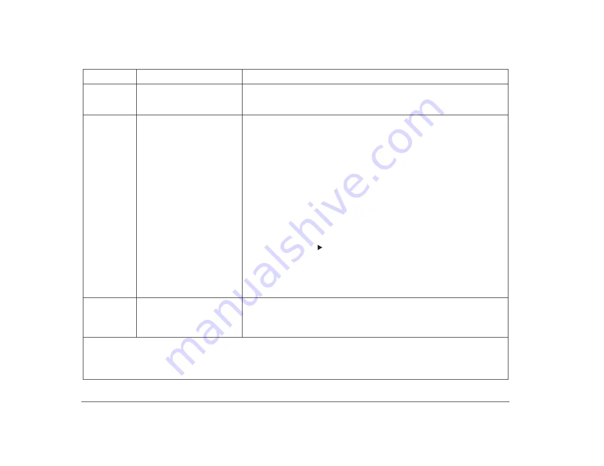
Error codes, descriptions, and corrective actions
161
Bad CMOS Battery
Make sure the battery is installed correctly. If the error continues, install a new
battery. For instructions on installing the battery, see “Replacing the battery” on
page 114.
162
Configuration Error
Configuration Change Has
Occurred
• If you are using Rapid Resume, complete the following steps:
- If you have not changed your hardware (installed or removed an option),
check your Services and Support Guide for information on obtaining
service.
Note:
Any work that you did not save before the computer was turned off
cannot be retrieved.
- If you have changed your hardware (installed or removed an option), press
the on/off button on the system unit to turn it off. Return the hardware to its
previous configuration, wait 10 seconds, and then turn the system unit on
again. If the error does not reoccur, save any work that you want to keep
and reinstall your hardware. If the error occurs again, check your Services
and Support Guide for information on obtaining service.
• If you are not using Rapid Resume:
- Press Enter while the error message is displayed to start the Configuration/
Setup Utility. Look through the Configuration/Setup Utility and verify that
the options with
next to them were supposed to change. If so, choose
Save Settings at the bottom of the Configuration/Setup Utility main menu
and press Enter. Then exit the Configuration/Setup Utility. For more
information on using the Configuration/Setup Utility, see page 63. If
options changed that were not supposed to, check your Services and
Support Guide for information on obtaining service.
163
Date and Time Incorrect
The clock module on the system board may not be set correctly. To set the
correct date and time, press Enter while the error message is displayed to enter
the Configuration/Setup Utility. For instructions on using the Configuration/
Setup Utility, see page 63.
Table 9: Error codes, descriptions, and corrective actions (Continued)
Error Code
Description
Here’s what to do:
Notes
:
1. An
X
shown as part of the error code in this table represents any number between 0 and 9.
2. If any of these errors continue after taking the actions listed, check your Services and Support Guide for information on
obtaining service.
Содержание Aptiva
Страница 1: ...Hardware Handbook...
Страница 12: ...2 Part 1 Reference information...
Страница 24: ...14 Performance tips...
Страница 32: ...Controlling the volume on multimedia systems 22...
Страница 50: ...40 Modem regulations...
Страница 88: ...78 Features of the Configuration Setup Utility...
Страница 90: ...80 Part 2 Installing options...
Страница 92: ...82 Identifying parts of the system unit Identifying parts of the system unit 8 9 10 11 12 13 7 3 4 2 1 5 6...
Страница 112: ...102 Installing and removing a hard disk in bay 4...
Страница 130: ...120 Appendix A...
Страница 136: ...126 Index...


