background image

7.1

Locate the rack-mounting hardware kit, the cable-management arm, and the slide
rail assemblies that were included with your server.

7.3

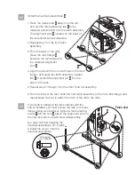
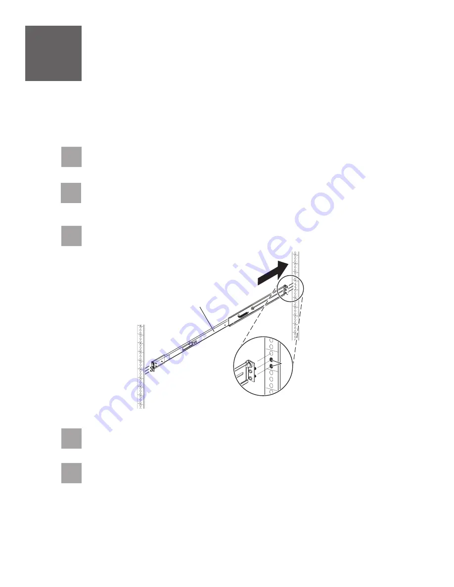
Insert the right slide rail

into the back-right rack mounting flange

holes, with

the rail pins protruding through the flange.

A

B

7

Install the slide rail assemblies

If you do not have enough space around your rack to open the front and back doors
completely, remove the doors before starting this task to allow adequate access.

If you are installing your server using fixed rails, go to task 4

Install the fixed rail assemblies.

7.2

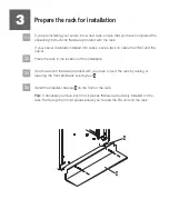
Determine where in the rack to place the server. Remove any filler panels
necessary to allow adequate access to the location where you will install your
server.

B

7.4

Press on the end of the slide rail

to compress the spring-loaded mechanism,

and insert the slide rail into the front-right rack mounting flange

holes.

A

B

A

7.5

Repeat steps 7.3 and 7.4 for the left slide rail.

Содержание 9115-505

Страница 1: ...Quick start guide for IBM System p5 505 9115 505 IBM Systems...

Страница 2: ...accompanies it 1 Before you begin Use safe practices when lifting This Quick start guide contains an abbreviated set of setup instructions designed to help you quickly unpack and set up a standard sy...

Страница 3: ...parts Your IBM reseller IBM Rochester manufacturing automated information line at 1 800 300 8751 United States only Directory of worldwide contacts at www ibm com planetwide Select your location to vi...

Страница 4: ...ation of the installation Use the wrench that was provided with your rack to level the rack by raising or lowering the front and back leveling feet Install the stabilizer bracket on the front of the r...

Страница 5: ...f the rack Note If you are installing your server using slide rails go to task 7 If you are installing your server into a tapped hole rack follow the instructions in the IBM Systems Hardware Informati...

Страница 6: ...E C D 1 3 4 Repeat steps 1 through 4 for the other fixed rail assembly From the front of the rack slide the front latch assembly to the front rack flange and repeat steps 3 and 4 to attach the front o...

Страница 7: ...he rack the rail lock pins extend out and lock into place A B Install the server onto the fixed rail assemblies 5 Before installing the server onto the fixed rail assembly ensure that the leveling fee...

Страница 8: ...o the left and lock it into place by pulling the locking cam back away from the server C 6 Install the cable management arm Tip After you have cabled your server use the straps that are attached to th...

Страница 9: ...nd back doors completely remove the doors before starting this task to allow adequate access If you are installing your server using fixed rails go to task 4 Install the fixed rail assemblies 7 2 Dete...

Страница 10: ...o the back right rail using screw Finger tighten the screw J K I 7 6 From the front of the rack install the latch strike onto the front of each slide rail using the captive screw Finger tighten the ca...

Страница 11: ...from falling forward Tip Read this entire task before completing any individual steps CAUTION This part or unit is heavy but has a weight smaller than 18 kg 39 7 lb Use care when lifting removing or...

Страница 12: ...er tighten the screws that you installed in steps 7 7 through 7 8 8 7 If you are securing the server to the rack for transport insert and tighten the two screws to secure the server into the rack F Yo...

Страница 13: ...agement arm mounting plate until the hinge brackets snap into place D E F 9 Install the cable management arm 9 2 A B C Align the tabs on the cable management arm mounting plate with the slots on the b...

Страница 14: ...n I G I H Important Performing this step prevents the server from sliding out of the rack You must remove the latch pin prior to sliding the server out of the rack H Tip After you have cabled your ser...

Страница 15: ...stems Hardware Information Center and return to this guide when you are ready to begin cabling your HMC For details about how to access the information center see task 12 f you are not using an HMC to...

Страница 16: ...d electrical outlet to avoid electrical shock C018 Route the cables through the cable management arm on the server and secure the cables with the straps provided If you are not using a modem skip to s...

Страница 17: ...ots of your server and PC Cable the server and access the Integrated Virtualization Manager CAUTION This product is equipped with a 3 wire two conductors and a ground power cable and plug Use this pow...

Страница 18: ...168 2 147 192 168 3 147 For example if you connected your PC to HMC1 the IP address for your service processor might be 192 168 2 1 and the subnet mask would be 255 255 255 0 Set the gateway IP addre...

Страница 19: ...gs and continue system server firmware boot 1 2 3 4 In the ASMI navigation area expand Click Select in the AIX Linux partition mode boot field Click Power Restart Control Power On Off System Continue...

Страница 20: ...the system management services SMS menu is displayed in the terminal session over the connection that you set up in step 11 1 choose and follow the menu options to set the optical drive as the initial...

Страница 21: ...on Initial server setup Create a customized initial server setup checklist You have completed the basic tasks to set up your server You can now access the Follow these steps to create a customized che...

Страница 22: ...s infocenter References in this publication to IBM products or services do not imply that IBM intends to make them available in every country or region IBM the IBM logo POWER and System p5 are tradema...

Отзывы: