


Installing
or
Replacing
a
Power
Supply
with
the
System
Power
On
The
system
power
can
remain
on
when
a
second
power
supply
installed
or
when
one
of
two
power
supplies
present
in
the
system
is
replaced.
To
install
a
second
power
supply,
or
to
replace
a
failing
power
supply
when
two
are
present
in
the
system,
do
the
following:
1.
If
a
failing
power
supply
is
present,
disconnect
the
power
cable
from
the
failing
power
supply
at
the
rear
of
the
system.
2.
Place
the
system
into
the
service
position
as
described
in
“Placing
the
Model
275
into
the
Service
and
Operating
Position”
on
page
248.
3.
Remove
the
service
access
cover
as
described
in
“Removing
the
Service
Access
Cover”
on
page
249..
4.
Ensure
the
power
supply
bay
is
empty
by
doing
one
of
the
following:
a.
Remove
the
power
supply
filler
by
grasping
the
handle
and
pulling
the
filler
inward
and
then
up
and
out
of
the
system.
b.
Remove
a
failing
power
supply
by
doing
the
following:
1)
Remove
the
power
cable
from
the
rear
of
the
failing
power
supply.
2)
Grasp
the
ends
of
the
power
supply
handles,
and
press
the
retractable
spring-activated
portion
of
each
handle.
This
action
releases
the
spring
latch
located
on
the
bottom
side
of
each
handle.
See
the
following
illustration.
3)
Lift
the
power
supply
release
handles
until
they
are
perpendicular
(90
degrees)
to
the
top
of
the
power
supply.
By
placing
the
handles
perpendicular
to
the
top
of
the
power
supply,
the
base
or
hinged
portion
of
each
handle
acts
as
a
cam
and
helps
pry
the
power
supply
from
its
connector
located
on
the
system
backplane.
4)
After
the
power
supply
is
released
from
its
connector,
pull
the
power
supply
straight
out
from
the
system.
5.
Grasp
the
power
supply
handles
located
on
top
of
the
new
power
supply.
Pivot
the
power
supply
handles
upward
to
90
degrees.
This
action
puts
the
handle
cams
into
the
correct
position
to
help
seat
the
power
supply
into
its
connector.
6.
Carefully
insert
the
new
power
supply
into
the
power
supply
bay.
7.
Lower
the
power
supply
handles,
carefully
pressing
the
power
supply
into
the
connector.
The
spring
latch
located
on
the
underside
of
each
handle
will
snap
into
place,
indicating
that
the
power
supply
is
seated
correctly
and
locked
into
position.
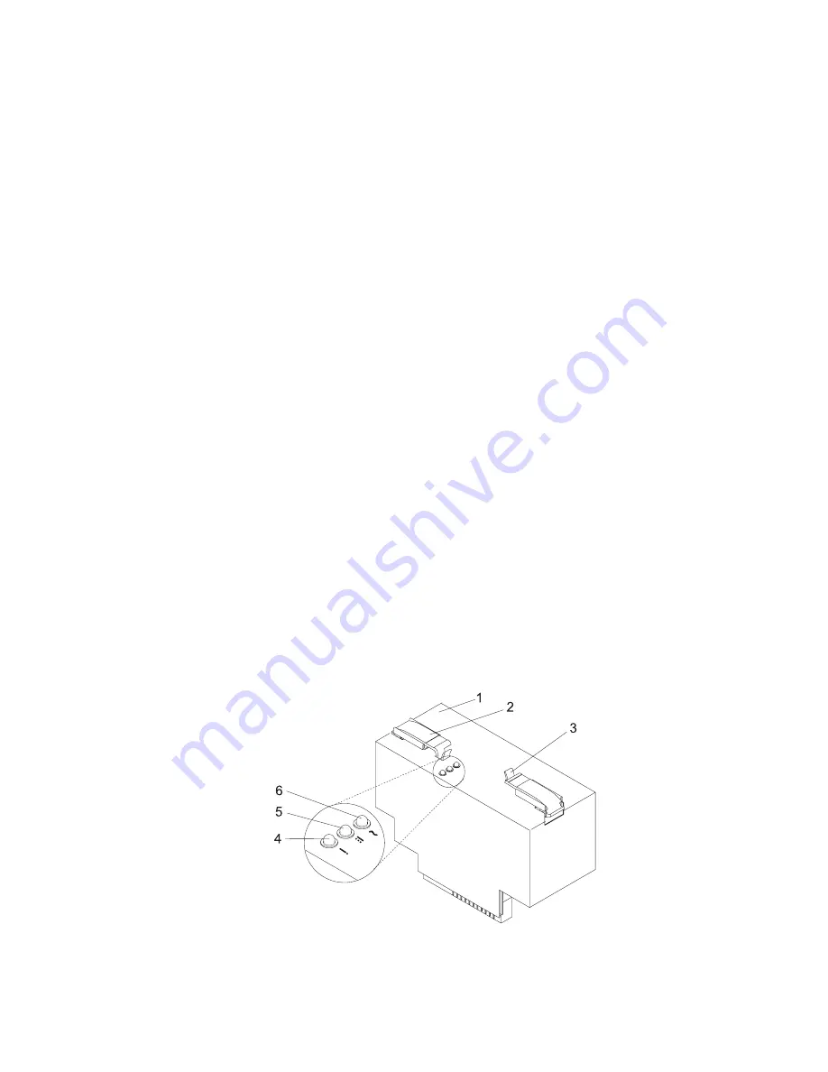
1
Power
supply
4
Fault
LED
(Amber)
2
Power
supply
handle
(2)
5
DC
Good
LED
(Green)
3
Spring
Latch
(2)
6
AC
Good
LED
(Green)
Chapter
9.
Removal
and
Replacement
Procedures
291
Содержание 9114-275 - IntelliStation POWER 275
Страница 1: ...IntelliStation POWER 9114 Model 275 Service Guide SA38 0636 00 ...
Страница 2: ......
Страница 3: ...IntelliStation POWER 9114 Model 275 Service Guide SA38 0636 00 ...
Страница 14: ...xii IntelliStation POWER 9114 Model 275 Service Guide ...
Страница 16: ...xiv IntelliStation POWER 9114 Model 275 Service Guide ...
Страница 50: ...32 IntelliStation POWER 9114 Model 275 Service Guide ...
Страница 58: ...40 IntelliStation POWER 9114 Model 275 Service Guide ...
Страница 81: ...Yes Go to Step 1321 16 on page 64 Chapter 3 Maintenance Analysis Procedures MAPs 63 ...
Страница 210: ...192 IntelliStation POWER 9114 Model 275 Service Guide ...
Страница 246: ...228 IntelliStation POWER 9114 Model 275 Service Guide ...
Страница 319: ...Chapter 10 Parts Information This chapter contains parts information for the IntelliStation POWER 9114 Model 275 301 ...
Страница 320: ...System Parts 302 IntelliStation POWER 9114 Model 275 Service Guide ...
Страница 330: ...312 IntelliStation POWER 9114 Model 275 Service Guide ...
Страница 332: ...314 IntelliStation POWER 9114 Model 275 Service Guide ...
Страница 336: ...318 IntelliStation POWER 9114 Model 275 Service Guide ...
Страница 340: ...322 IntelliStation POWER 9114 Model 275 Service Guide ...
Страница 375: ......
Страница 376: ... Printed in U S A July 2003 SA38 0636 00 ...
Страница 377: ...Spine information IntelliStation POWER 9114 Model 275 IntelliStation POWER 9114 Model 275 Service Guide SA38 0636 00 ...