10
i3-TRNG-CAMS-Ax47R_67R-UM.indd
Rev. 171109
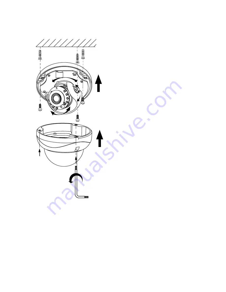
4.4 Surface Mounting
This installation method is suitable for both indoor and outdoor applications.
1. Attach the supplied Drill Template to the
mounting surface.
2. Drill 3 (three) 4.5 mm (0.2”) holes at the
marked template positions on the mounting
surface.
3. Insert the supplied screw anchors into the
holes on mounting surface.
4. Based on installation requirements, you
may route the cable through the cut-
out opening on the side of the camera’s
mounting base. In that case, no additional
openings are required on the mounting
surface. Alternatively, drill a 13mm (0.5”)
circular opening in the mounting surface,
corresponding to the “Cable hole” of the
drill template.
See section 4.4 fore more
info.
5. Disassemble the camera by removing the
dome bubble. Use the provided security
Torx key to loosen three silver screws
securing the dome bubble to the camera’s
mounting base. Do not completely remove
the screws from the bubble. Lift the dome
bubble off and set aside.
6. Route the camera cabling according to
installation requirements, then use a
Phillips screwdriver to secure the camera
module to the mounting surface with the
provided mounting screws, if suitable.
7. Connect the wiring.
8. Adjust the lens angle by rotating and panning the camera lens base. Do not over-
rotate the camera lens beyond the stop point to avoid damage to the camera.
See
section 4.1 for more info.
Tip: For the ease of setup, lift off the camera liner while adjusting the lens position.
Once the desired view has been achieved, replace the camera liner until it snaps
into place.
9. Replace the camera dome bubble housing on top of the camera module.
10. Use the supplied Torx bit to re-tighten 3 silver screws securing the dome bubble
housing to the camera module.
11. Remember to use sealant to maintain IP67 rating in outdoor installations.


