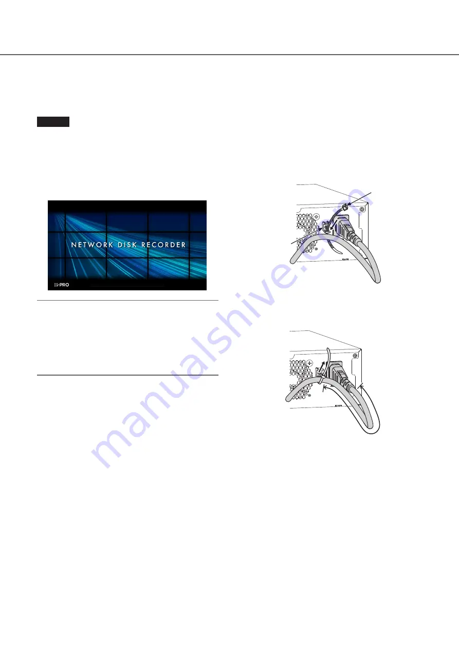
background image

20

Turn on the devices

Turn on the power of the recorder

Turn on the power of the recorder. First, turn on the power of the monitor.

Step 1

Connect the included power cord to the power cord 
inlet on the rear panel of the recorder, and insert the 
power plug to an outlet whose rating is as follows.

100 V - 240 V AC, 50 Hz/60 Hz


The [OPERATE] indicator on the front of the recorder will 
light, the system check will start, and the startup window 
will be displayed on the main monitor.

Important:

•  Never turn off the power of the recorder during startup.
•  Insert the power cord fully into the power supply terminal 

so that it will not loosen or come out.

•  Fix the power cord firmly at 15 cm to 20 cm {5-7/8 to 

7-7/8 inches} from the plug with the included cable 
clamp (for power cord) to prevent the cable from 
unplugging.

How to prevent power cord 

disconnection

Fix the power cord at 15 cm to 20 cm {5-7/8 to 7-7/8 
inches} from the connector with the included cable clamp 
(for power cord) passed through the clamp mount.

Cable clamp
(for Power cord)

Clamp mount

 Pass the cable clamp (for power cord) through 
the slit on the lower side of the clamp mount.

15 cm

20 cm

{5-7/8 ~ 7-7/8 inches}

Tighten the cable clamp 15 cm to 20 cm from 
the power cord connector to fix it to the clamp 
mount. Cut the excessive part of the cable 
clamp if necessary.

Содержание WJ-NU301K Series

Страница 1: ...abbreviated in some descriptions in this manual Installation Guide Network Disk Recorder Model No WJ NU301K Series The Operating Instructions and Important Information PDF is on our support website h...

Страница 2: ...nstall the hard disk drives 12 When replacing the hard disk drives 13 2 Rack mounting 14 Installation procedure 14 3 Connections 15 Connection of cameras a mouse and a PC 15 Connection of monitors 16...

Страница 3: ...ents REC event Advanced setup Configure the settings relating to monitors Monitor Configure the settings relating to network Network Configure the settings relating to the user management User managem...

Страница 4: ...rt numbers versions and network cameras that can be connected hereinafter referred to as cameras and information such as the addition of functions by upgrading the software of this product please refe...

Страница 5: ...y cause deformation discoloration and malfunction Keep this product away from water and moisture i PRO Co Ltd assumes no responsibility for injuries or property damage resulting from failures arising...

Страница 6: ...signed to cool the hard disk drives by drawing in air from the front Avoid placing this product near noise sources If the cables are placed near noise sources such as fluorescent lamps noises may be p...

Страница 7: ...ue can be changed using the mouse wheel When no operation is made for 10 seconds or more the mouse cursor will be hidden The mouse cursor will be displayed again when the mouse is moved This section e...

Страница 8: ...rsor in the entry field A a button This button changes the characters to be entered between capital letters and small letters Next button Changes the keys to be displayed for character entry The displ...

Страница 9: ...etup pages Easy Start button It is possible to configure the minimum settings required to operate the recorder such as date time and cam era registration Basic setup Setup page buttons Each Basic setu...

Страница 10: ...s The settings can be done through a web browser on the PC Refer to the Operating Instructions PDF The PC is required for reading the Important Information the Operating Instructions PDF and camera se...

Страница 11: ...Example of an operational screen 11 Operations flow continued...

Страница 12: ...y procured Contact your dealer for purchasing installing and replacing the hard disk drives Since the basic installation method is the same the illustrations for STEP3 to STEP7 in the following proced...

Страница 13: ...setup menu the Maintenance page the HDD information tab Operating Instructions PDF 1 Installation of the hard disk drive continued Step 6 Make sure that the cable passes through the HDD HOLDER BASE sl...

Страница 14: ...top and bottom of the product Do not put doors on the front of the rack or block the sides Use a rack equivalent to the EIA standard for mounting this product EIA standard equivalent manufactured by...

Страница 15: ...ded Switching hub Network Ethernet cable locally procured category 5e or above straight IP address 192 168 0 x 0 1 250 255 Except the camera s IP address Subnet mask 255 255 255 0 Default gateway 192...

Страница 16: ...SUB terminal using an HDMI cable locally procured Main monitor HDMI Sub monitor HDMI HDMI cable locally procured HDMI cable locally procured Recorder Note Use a High Speed HDMI Cable Also when the ma...

Страница 17: ...supplied at an event occurrence Open collector output 24 V DC max 200 mA max 8 Camera error output Signal output upon detection of a camera error 9 HDD error output Recording error output Signal outpu...

Страница 18: ...utput Recording error output Signal ground 6 9 Alarm connection example When a signal output from the other device is supplied to the Alarm input 1 terminal pin No 1 or Alarm input 2 terminal pin No 2...

Страница 19: ...amera reset L active Alarm output The set time on the setup menu L active General purpose input output when set to input 100 ms or more For N O L active For N C H active General purpose input output w...

Страница 20: ...er cord fully into the power supply terminal so that it will not loosen or come out Fix the power cord firmly at 15 cm to 20 cm 5 7 8 to 7 7 8 inches from the plug with the included cable clamp for po...

Страница 21: ...eep informa tion on the administrator name and the password in a safe place where nobody can see it except you Contact your dealer for initializing When turn off the power of the recorder Follow the p...

Страница 22: ...ras Check the user level settings of these users Operating Instructions Part of the displayed image is missing This phenomenon is caused by dispersion of display area on the monitor This is not a malf...

Страница 23: ...tact your dealer The error indicator blinks red A system error occurred Contact your dealer Authentication error of the camera is displayed When a new camera is detected by Easy Start the username and...

Страница 24: ...r more information about collection and recycling please contact your local municipality Penalties may be applicable for incorrect disposal of this waste in accordance with national legislation Note f...

Отзывы: