8
4.3 NGRS-XX RESISTOR SENSOR
The NGRS-XX resistor sensor must be selected from those available from I-GARD and must be rated for the system
voltage in which it will be installed.
4.3.1 Location
The NGRS-XX resistor sensor should be mounted near the system transformer, along with the ZSCS and the NGR.
4.3.2 Mounting
The overall dimensions of the NGRS-XX resistor sensor are 89 mm x 65 mm x 71 mm (for the low voltage units).
A metal mounting bracket extends from one side of the housing. The bracket has two 6 mm mounting holes in it
through which bolts or self threading screws can be used to mount the NGRS-XX resistor sensor to a flat surface.
Refer to Figure 4 for higher voltage NGRS resistor sensors.
4.3.3 CONNECTIONS
The neutral terminal of the NGRS-XX resistor sensor must be connected to the ungrounded end of the NGR. This is
the same connection point as is connected to the system transformer’s neutral. Refer to Figure 2.
The R terminal of the NGRS-XX resistor sensor must be connected to terminal 45 of the SIGMA-MD monitor relay as
shown in Figure 2. The G terminal of the NGRS-XX resistor sensor should be connected to a suitable ground point.
This grounding point should be separate from the ground path from the NGR so that the ground path from the NGR
is monitored as well as the NGR itself.
4.4 CONFIGURATION OF SIGMA-MD MONITOR RELAY AND NGR
The SIGMA-MD monitor relay has settings for the let-through current, ground fault trip current level and ground
fault time delay. These settings may be specified in the installation requirements. However, the let-through current
and ground fault trip current level are, in part, dependent on conditions that can only be determined at the time of
installation or if and when there are changes to the operating environment.
One of the operating conditions that impact the relay settings is the amount of leakage or charging current in
the system. This may vary from one installation to another or, as noted above, when there are changes to the
operating environment.
As the let-through current measured by the zero sequence current sensor will be the vector sum of any leakage
currents or charging currents normally in the system and any ground fault currents that may be present, it is
important that the leakage currents or charging currents normally in the system be taken into consideration
when setting the relay’s ground fault trip points. Failure to take the leakage currents or charging currents into
consideration may result in false tripping due to the low let-through current settings.
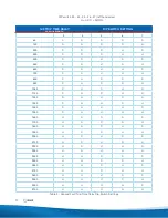
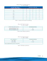
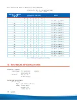
The ground fault trip current level is set as a percentage of the let-through current through the NGR. The ground
fault trip current level setting available are: 50 %, 40%, 30%, 25%, 20%, 15%, 10% and 5%.
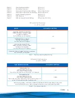
The SIGMA-MD monitor relay has sixteen settings for the let-through current, ranging from 50 A to 800 A with an
I-GARD TxA type ZSCS.


