21
DIP SWITCH SETTINGS
Trip Level:
8 settings: 5%, 10%, 15%, 20%, 25%, 30%, 40%, and 50% of the set NGR current setting
Trip Time:
32 settings, 0-60 msec., 150 msec. to 3.15 sec. in 100 msec. steps
Accuracy:
Repeat: ±1%
Trip Time:
±10%, ±10 msec.
Trip Current:
±10%
Meter Output: ±2% at full scale.
NGR FAULT CIRCUIT
NGRS Input:
Non-isolated. One side of the NGRS input, terminal 20, is internally connected to ground.
NGR Let-Through Current:
Dip switch settings from 50 A to 800 A in 50 A increments.
NGR Trip Resistance:
(when the NGR current is high enough to allow
measurement of the NGR)
An increase to more than 150% (300% when in high
tolerance mode) or a decrease to less than 66% of the
NGR nominal resistance.
NGR Trip Resistance:
(when the NGR current is too low (<1%) to allow
measurement of the NGR)
Simple continuity, i.e. determines whether the NGR
circuit is open or presents some resistance.
Trip Time:
Less than 60 seconds per CAN/CSA-M421-00.
Typically 3.5 seconds -0 + 100 msec.
Up to 10 seconds under certain conditions.
Accuracy:
NGR Trip Resistance limits in Ohms ±20%.
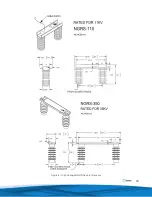
NGRS-XX RESISTOR SENSOR (Various versions are available)
Voltage:
Various system voltages
Resistance:
As determined by the system voltage
Dimensions:
Typical: 89 mm (3.5 in.) x 65 mm (2.5 in.) x 71 mm (2.85 in.)
ANALOG METER GFU-AM1
Movement:
0-1 mA
Impedance:
200 Ohms Max.
Scale:
0-100%
Size:
65
mm
(3•in.)
The meter display is proportional to the measured current expressed as percentage of the set NGR let-through current.
Note: A digital meter may be connected to instead of the I-GARD GFU-AM1, however it may required a separate
power supply.
APPLICABLE STANDARDS
CSA
CSA C22.2 No 0
CSA C22.2 No 14 Industrial Equipment
CSA C22.2 No. 144 Ground Fault Interrupters CSA Polymeric Enclosures
CSA-M421-00 Use Of Electricity In Mines
I-GARD Corporation reserves the right to change specifications of its products without notice.


